
Vacuum Unit, Vacuum Pump System ZX Series
Product Description
Vacuum unit and vacuum pump system capable of manifolding.
[Features]
・ For electronic parts and small accessory precision parts up to 100 g
・ Ideal combination of functions possible due to modular design
・ Compact and lightweight (120 g when full set of functions) makes it ideal for actuator mounting
Download

Vacuum Unit, Vacuum Pump System ZX Series Specifications
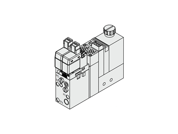
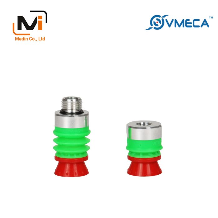
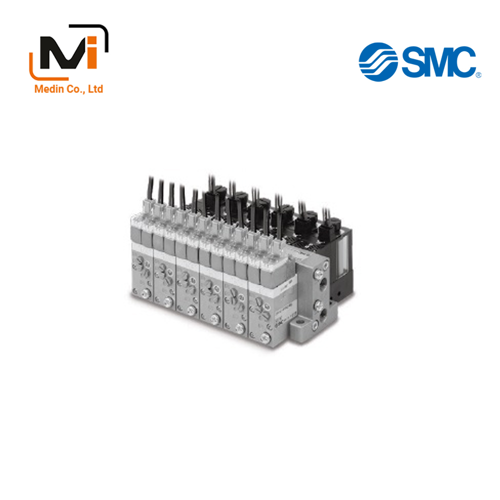
ZX100-K15LZ-E□ external appearance
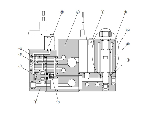
Vacuum Pump System structural diagram
Component Parts / Replacement Parts
| Number | Part Name | Material | Note |
|---|---|---|---|
| 1 | Poppet Valve Assembly | – | ZX1-PV-0 |
| 2 | Vacuum break flow adjusting needle | Stainless steel | ZX1-NA |
| 3 | Manifold base | Aluminum | – |
| 4 | Vacuum switch | – | ZSE2 and ZSE3 |
| 5 | Valve unit | – | ZX1-VB□□□□□□-D-□ |
| 6 | Interface plate | – | (PV) / (PS ⇔ PD) |
| 7 | Spring return | Stainless steel | – |
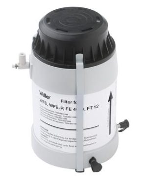
| Note)8 | Filter case | Polycarbonate | – |
| Number | Part Name | Material | Part Number |
|---|---|---|---|
| 9 | Pilot valve | – | Please refer to the catalog. |
| 10 | Filter element | PVA | ZX1-FE |
| 11 | Gasket | – | ZX1-FG |
| 12 | Filter Case Assembly | – | ZX1-FK-PC* |
*Component parts
Filter case, filter elements, tension bolts (including o-ring)
(Gasket mentioned in number 11 is not included.)
Note) Cautions when handling the filter case:
1) The case is made of polycarbonate, so do not use with or expose it to the following chemicals: paint thinner, carbon tetrachloride, chloroform, acetic ester, aniline, cyclohexane, trichloroethylene, sulfuric acid, lactic acid, water-soluble cutting oil (alkaline), etc.
2) Do not expose it to direct sunlight.