Transmitter / Time Delay Valve VR2110 Series
Product Description
Transmitter / Time Delay Valve VR2110 Series operates in a similar way to an electrical time delay relay.
[Features]
· The combination of an adjustable orifice and fixed flow allows the transmission of a pneumatic signal after a fixed time period (delay).
Download

Transmitters / Time Delay Valve VR2110 Series: Details

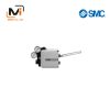
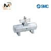
Transmitters / Time Delay Valve VR2110 Series: product images
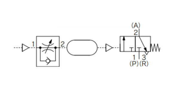
Transmitter / Time Delay Valve VR2110 Series JIS symbol
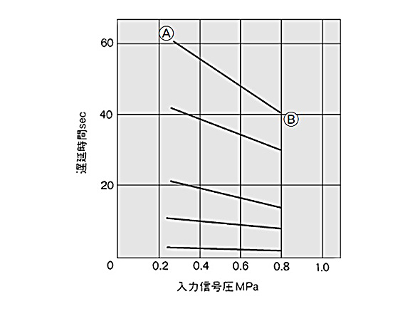
Input signal (PIL) vs. time delay
Example: Point A was set with an input signal pressure of 0.25 MPa and a delay time of 60 seconds. With the same status, if the input signal pressure is increased to 0.8 MPa, the delay time changes to point B (approximately 40 seconds).
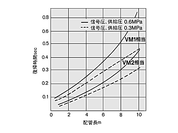
Piping length vs. release time when input signal (PIL) is OFF
If the input signal (PIL) is turned OFF, the release time for the time delay valve will change depending on the effective area of the valve and the length and diameter of the piping. Use the graph above as a reference.
Transmitter / Time Delay Valve VR2110 Series Specifications
Specifications/Model
| Model | VR2110-01 | |
|---|---|---|
| Supply pressure | 0 to 1.0 MPa | |
| Input signal pressure | 0.25 to 0.8 MPa | |
| Time delay | 0.5 to 60 s | |
| Repeatability * | ±10% F.S. (representative value) | |
| Operating and operating air temperature | -5 to 60°C (no freezing) | |
| Flow rate characteristics | C [dm3/(s·bar)] | 0.5 (P → A), 0.4 (A → R) |
| b | 0.2 (P → A), 0.15 (A → R) | |
| Connection port size | 1/8 | |
| Weight | 500 g | |
- *The dispersion is shown excluding the first actuation when actuated 4 times continuously.
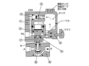
Structural Drawings
Release time
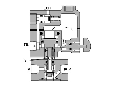
Actuated – before time set
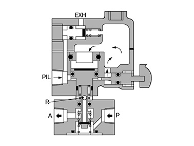
Actuated – after time set
| Number | Name | Materials | Additional notes |
|---|---|---|---|
| 1 | Valve main body | ADC | Platinum silver |
| 2 | Differential piston | Brass, NBR | Rubber lined |
| 3 | Exhaust piston | Brass, NBR | Rubber lined |
| 4 | Needle | Brass | – |
| 5 | Return spring | Steel wire | – |
| 6 | Valve main body | ZDC | Platinum silver |
| 7 | Plunger | POM | – |
| 8 | Valve | NBR | – |