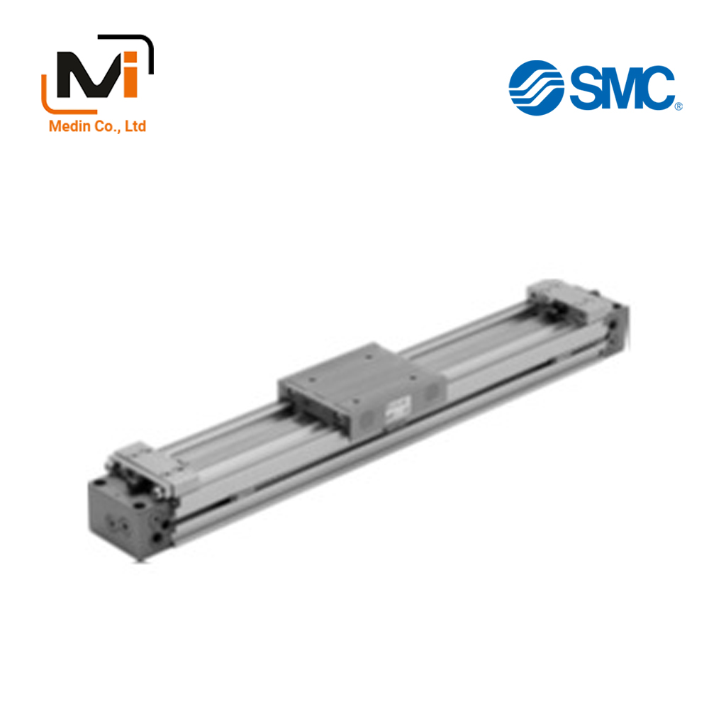
Mechanically Jointed Rodless Cylinder, Cam Follower Guide Type, MY1C Series
Product Description
An air slide table made by SMC
[Features]
· Capable of smooth operation even when there is an unbalanced load
· Moment-resistant and capable of supporting long strokes
Download

Details of Mechanical Joint Type Rodless Cylinder, Cam Follower Guide Type MY1C Series
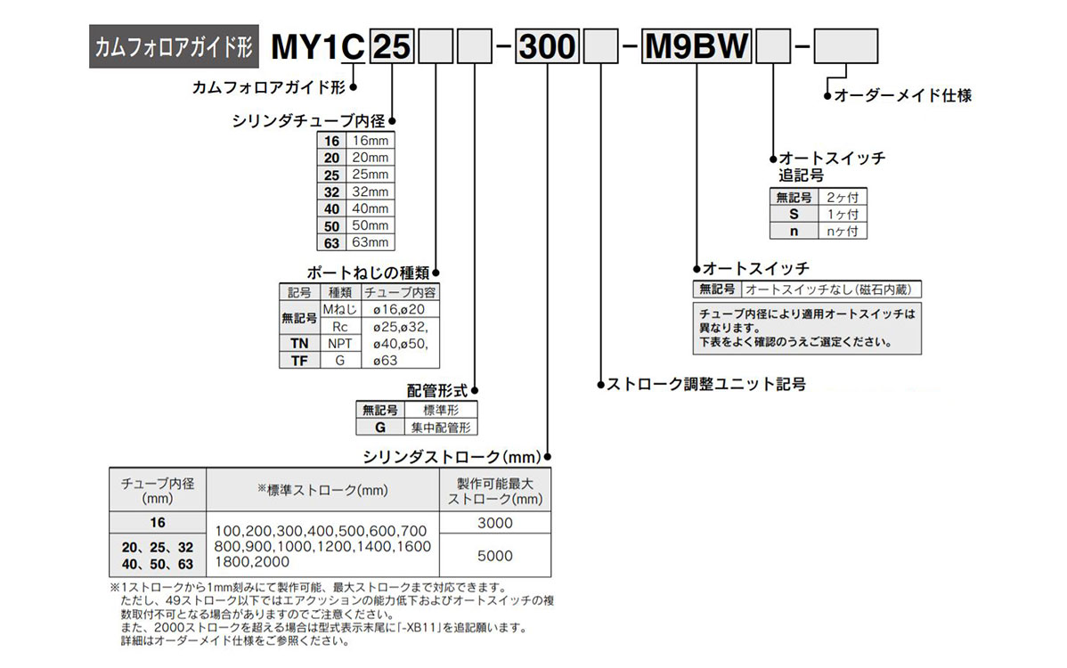
Model number examples
* Strokes can be manufactured in increments of 1 mm starting from 1 stroke up to the maximum stroke. However, note that if the stroke is 49 strokes or less, the air cushion capacity may decline and mounting multiple auto switches may not be possible.
* Please refer to the catalog for the stroke adjustment unit.
Standard Specifications
| Tube Internal Diameter (mm) | 16 | 20 | 25 | 32 | 40 | 50 | 63 | |
|---|---|---|---|---|---|---|---|---|
| Fluid | Air | |||||||
| Operation Type | Double-acting type | |||||||
| Operating Pressure Range | 0.15 to 0.8 MPa | 0.1 to 0.8 MPa | ||||||
| Proof Pressure | 1.2 MPa | |||||||
| Ambient and fluid temperature | 5 to 60°C | |||||||
| Cushioning | Air cushion | |||||||
| Lubrication | Not required | |||||||
| Stroke Length Tolerance | 1,000 or less (0~+1.8) 1,001 to 3,000 (0~+2.8) |
2,700 or less (0 to +1.8), 2,701 to 5,000 (0~+2.8) | ||||||
| Piping Connection Port Diameter | Front/side port | M5 × 0.8 | Rc 1/8 | Rc 1/4 | Rc 3/8 | |||
| Bottom port | ø4 (Port size 4 mm) | ø6 (Port size 6 mm) | ø8 (Port size 8 mm) | ø10 (Port size 10 mm) | ||||
Piston Speed
| Tube Internal Diameter (mm) | 16 to 63 | |
|---|---|---|
| No stroke adjustment unit | 100 to 1,000 mm/s | |
| Stroke adjustment unit | A unit | *1) 100 to 1,000 mm/s |
| L unit, H unit | *2) 100 to 1,500 mm/s | |
*1) Be aware that if the stroke adjustment allowance with the adjust bolt leveling mount increases, the air cushion capacity will decrease. Meanwhile, in ranges exceeding the air cushion stroke, the working piston speed will become 100 to 200 mm/s.
*2) The piston speed used for centralized piping is 100 to 1,000 mm/s.
*3) Use at a speed within the range of the absorption capacity. See catalog.
Theoretical Output Table
(Unit: N)
| Tube Internal diameter (mm) |
Pressure received Area (mm^2) |
Operating Pressure (MPa) | ||||||
|---|---|---|---|---|---|---|---|---|
| 0.2 | 0.3 | 0.4 | 0.5 | 0.6 | 0.7 | 0.8 | ||
| 16 | 200 | 40 | 60 | 80 | 100 | 120 | 140 | 160 |
| 20 | 314 | 62 | 94 | 125 | 157 | 188 | 219 | 251 |
| 25 | 490 | 98 | 147 | 196 | 245 | 294 | 343 | 392 |
| 32 | 804 | 161 | 241 | 322 | 402 | 483 | 563 | 643 |
| 40 | 1,256 | 251 | 377 | 502 | 628 | 754 | 879 | 1,005 |
| 50 | 1,962 | 392 | 588 | 784 | 981 | 1,177 | 1,373 | 1,569 |
| 63 | 3,115 | 623 | 934 | 1,246 | 1,557 | 1,869 | 2,180 | 2,492 |
*) Theoretical output (N) = pressure (MPa) × pressure receiving area (mm^2).
Weight Table
(Unit: kg)
| Tube Internal diameter (mm) |
Basic Weight |
Extra weight per 50 strokes |
Movable Part Weight |
Side support Bracket weight (Per pair) |
Stroke adjustment unit weight (Per unit) |
||
|---|---|---|---|---|---|---|---|
| A/B type | A unit Weight |
L unit Weight |
H unit Weight |
||||
| 16 | 0.67 | 0.12 | 0.22 | 0.01 | 0.03 | 0.04 | – |
| 20 | 1.06 | 0.15 | 0.31 | 0.02 | 0.04 | 0.05 | 0.08 |
| 25 | 1.58 | 0.24 | 0.41 | 0.02 | 0.07 | 0.11 | 0.18 |
| 32 | 3.14 | 0.37 | 0.86 | 0.04 | 0.14 | 0.23 | 0.39 |
| 40 | 5.60 | 0.52 | 1.49 | 0.08 | 0.25 | 0.34 | 0.48 |
| 50 | 10.14 | 0.76 | 2.59 | 0.08 | 0.36 | 0.51 | 3.38 |
| 63 | 16.67 | 1.10 | 4.26 | 0.17 | 0.68 | 0.83 | 1.08 |
Calculation method/example: MY1C25-300 A
- Basic weight: 1.58 kg
- Extra weight: 0.24/50st
- A unit weight: 0.07 kg
- Cylinder Stroke: 300st
1.58 + 0.24 × 300 ÷ 50 + 0.07 × 2≒3.16 kg
Specifications of options
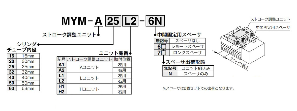
Model identification method for options, image
*1) Refer to the catalog for details on the adjustment range.
*2) ø16 (cylinder inner diameter: 16 mm) is available for A and L units only.
* The spacer is a mounting bracket for fixing the stroke adjustment unit at the intermediate position of the stroke.
Optional components
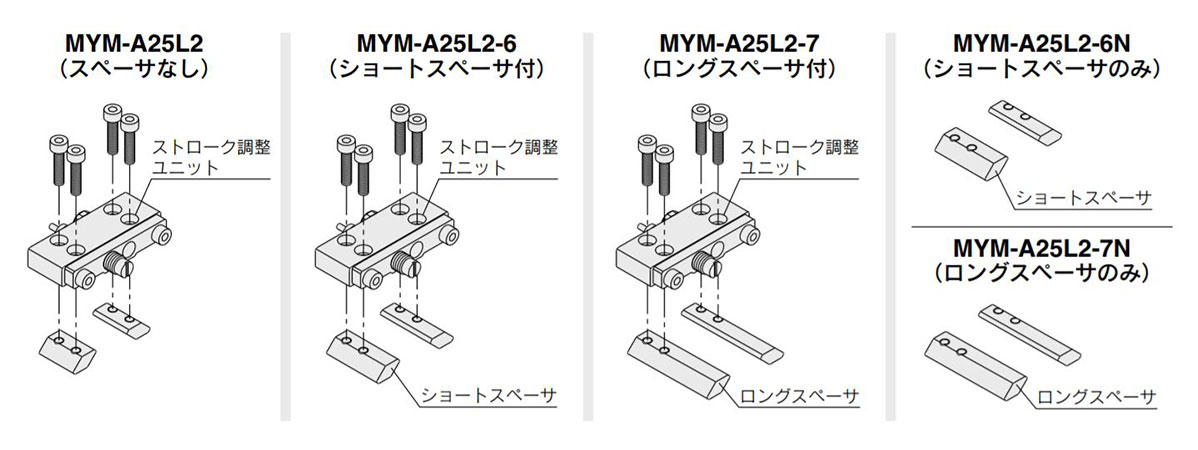
Optional component image
Side support model
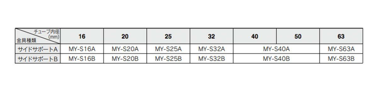
Image of side support model table
- * Please refer to the catalog for details such as dimensions.
- * The side support is a pair on the left and right.
Diagram
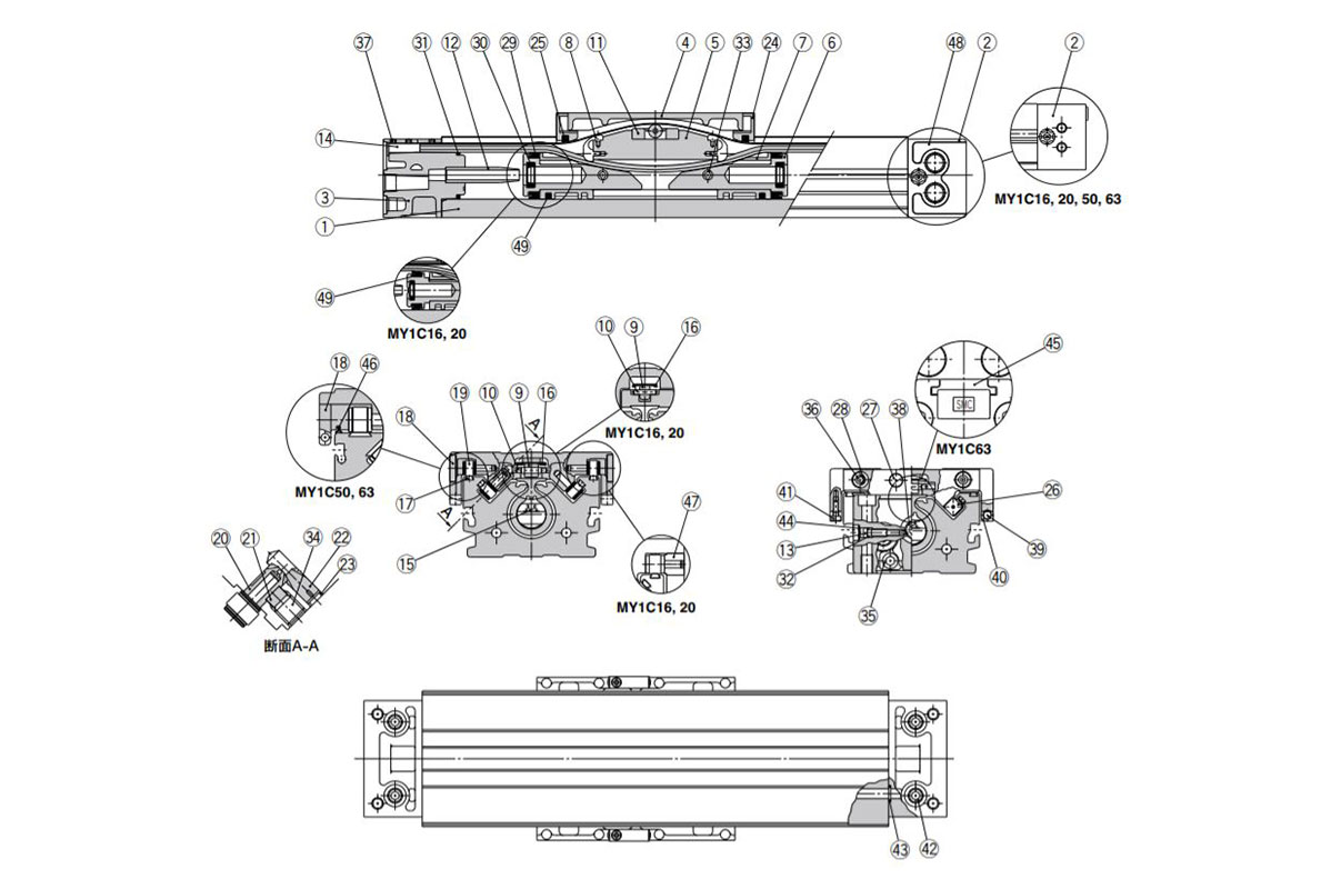
Structural drawing of Mechanical Joint Type Rodless Cylinder, Cam Follower Guide Type MY1C Series
Component parts table image
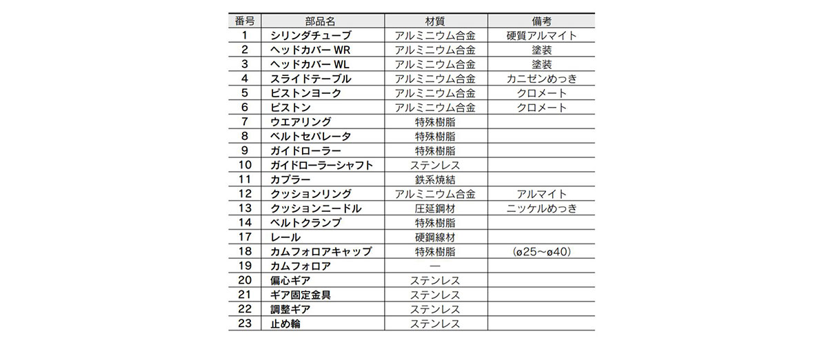
Image 1 for components parts table
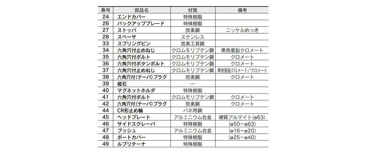
Image 2 for components parts table
Dimensions example of mechanical Joint Type Rodless Cylinder, Cam Follower Guide Type MY1C Series
Standard type / centralized piping type ø16 (Cylinder inner diameter: 16 mm) ø20 (Cylinder inner diameter: 20 mm)
(Units: mm)
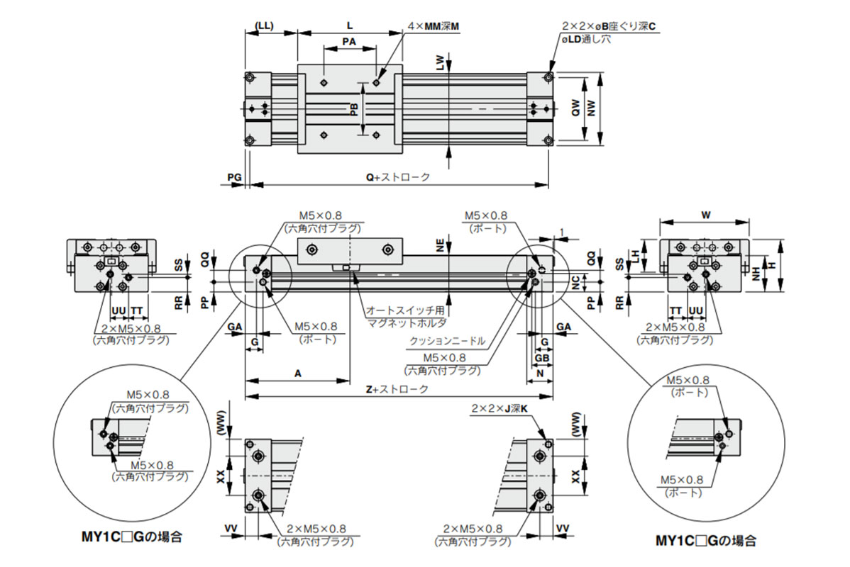
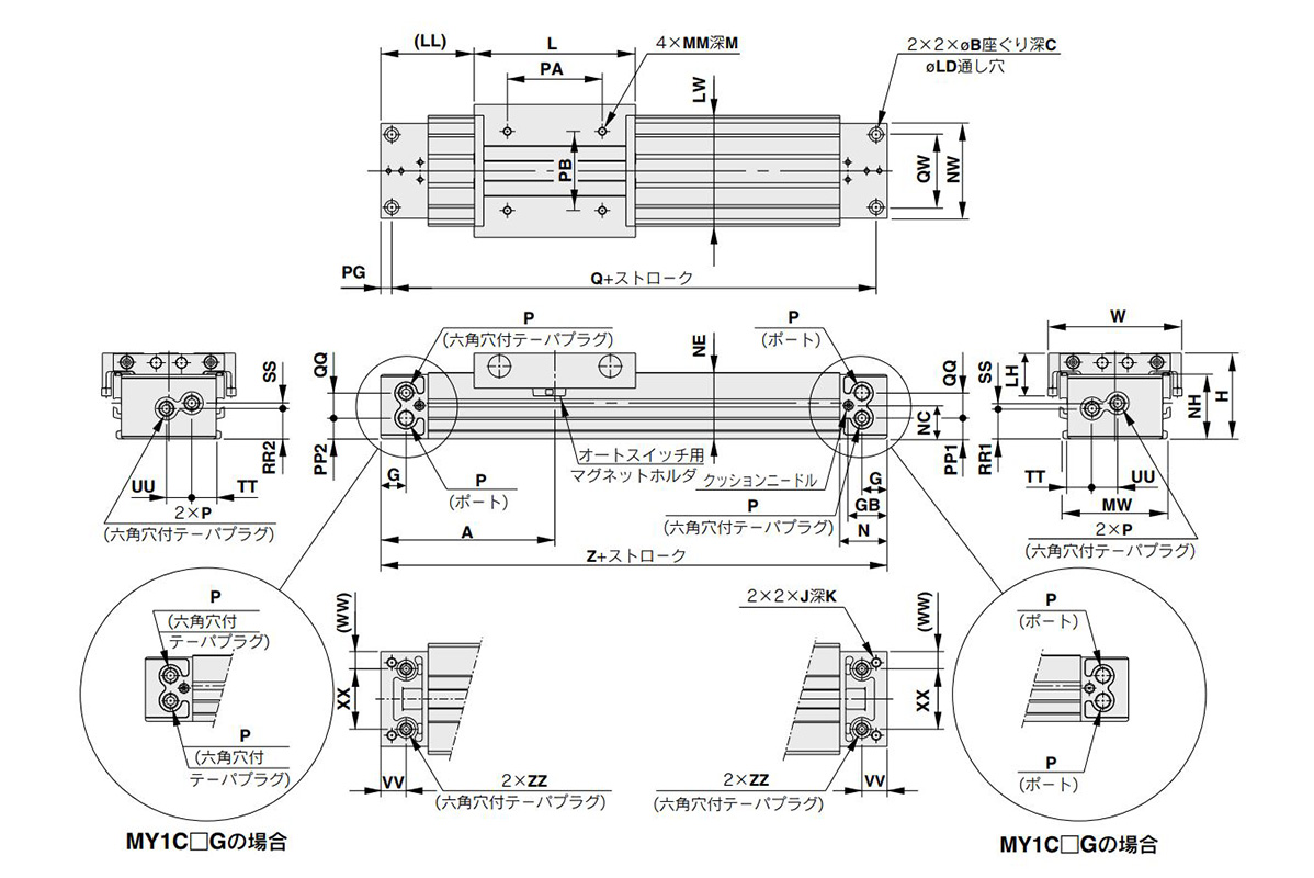
Dimensional drawing of MY1C16□/MY1C20□-Stroke
(Units: mm)
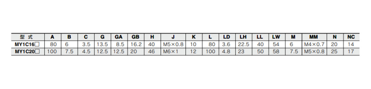
Dimension table image 1 of MY1C16□/MY1C20□
(Units: mm)
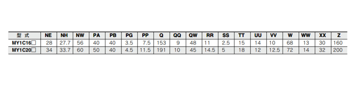
Dimension table image 2 of MY1C16□/MY1C20□
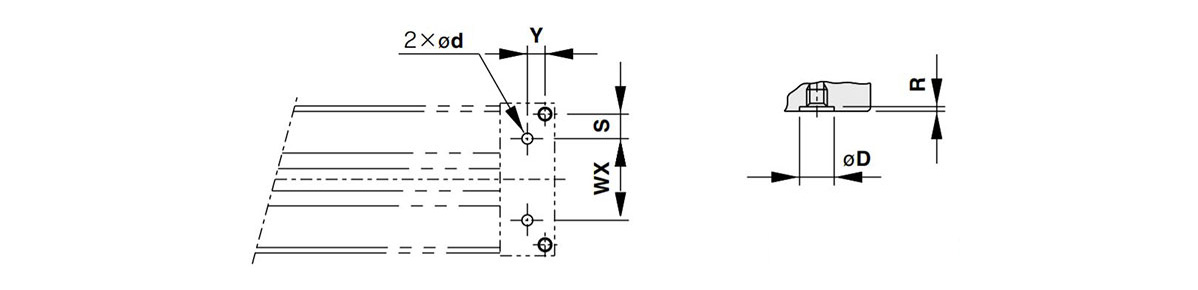
Piping hole dimensional drawing for centralized bottom piping of MY1C16□/MY1C20□ (right: Bottom side piping (Applicable O-ring)
(Units: mm)
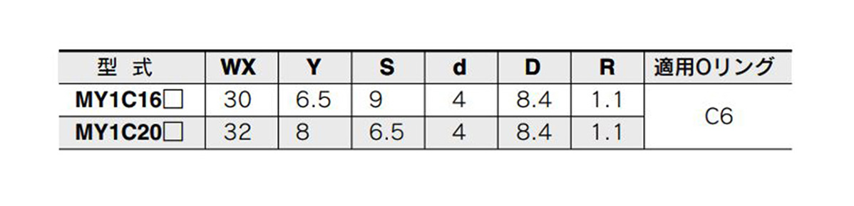
Image of piping hole dimension table for centralized bottom piping
* Please process the mounting surface with these dimensions.
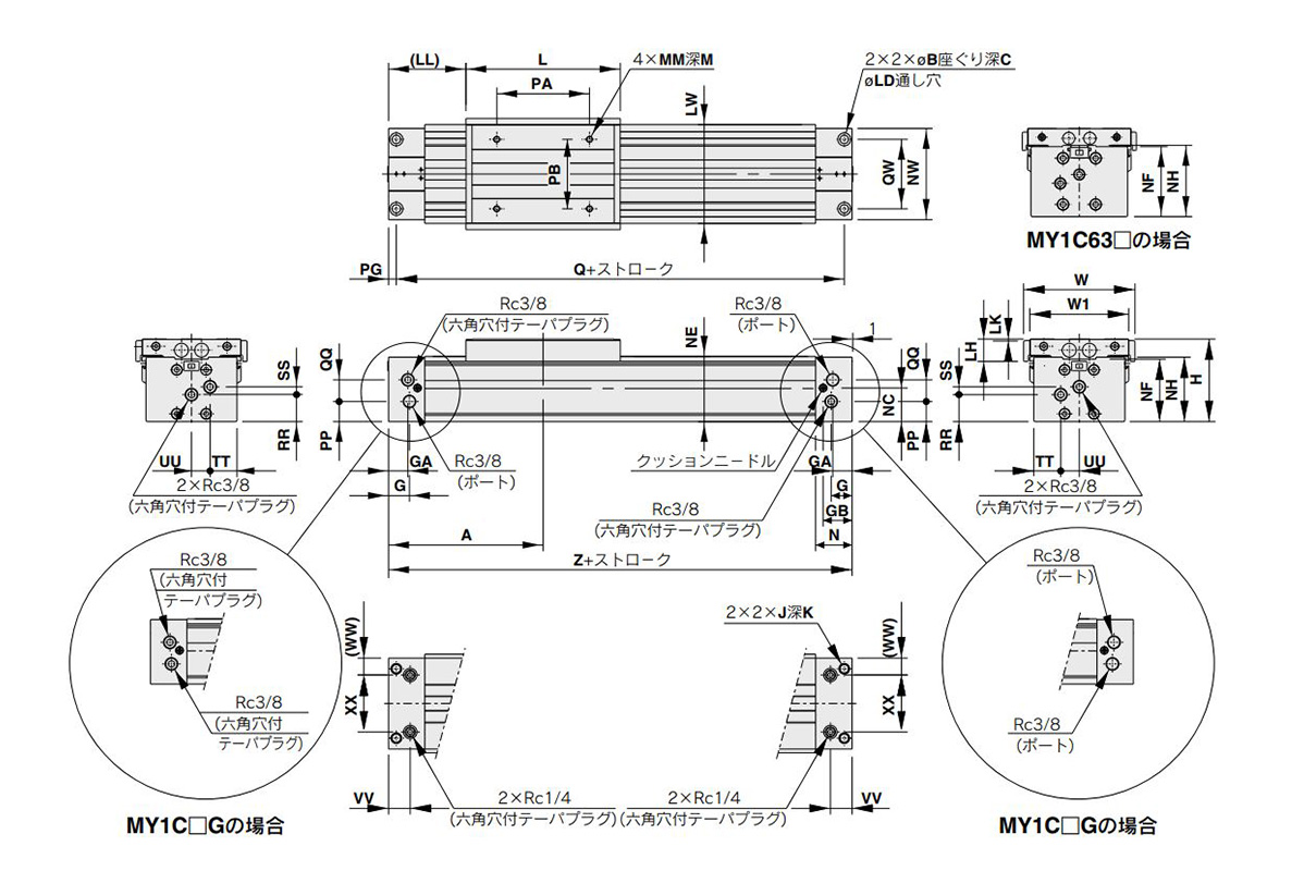
Standard type / centralized piping type ø25 (Cylinder inner diameter: 25 mm) ø32 (Cylinder inner diameter: 32 mm), ø40 (Cylinder inner diameter: 40 mm)
Dimensional drawing of MY1C25□/MY1C2532□/MY1C2540□-Stroke
(Units: mm)
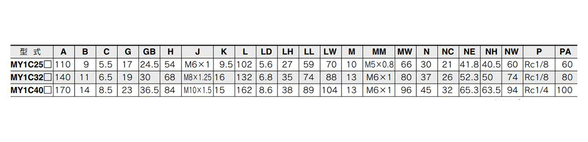
Dimension table image 1 of MY1C25□/MY1C2532□/MY1C2540□
* P indicates the cylinder supply port.
(Units: mm)
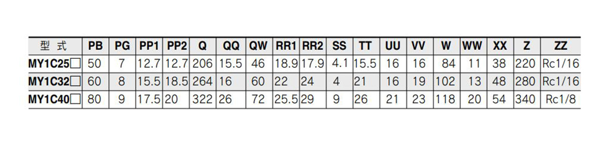
Dimension table image 2 of MY1C25□/MY1C2532□/MY1C2540□

Piping hole dimensional drawing for centralized bottom piping of MY1C25□/MY1C2532□/MY1C2540 (right: Bottom side (ZZ section) piping section (applicable O-ring)
(Units: mm)
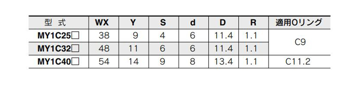
Image of piping hole dimension table for centralized bottom piping MY1C25□/MY1C2532□/MY1C2540□
* Please process the mounting surface with these dimensions.
Standard type/ Centralized piping type ø50 (Cylinder inner diameter: 50 mm) ø63 (Cylinder inner diameter: 63 mm)
Dimensional drawing of MY1C50□/MY1C5063□ Stroke
(Units: mm)
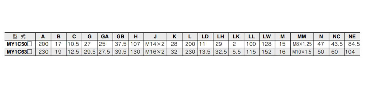
Dimension table image 1 of MY1C50□/MY1C5063□
(Units: mm)
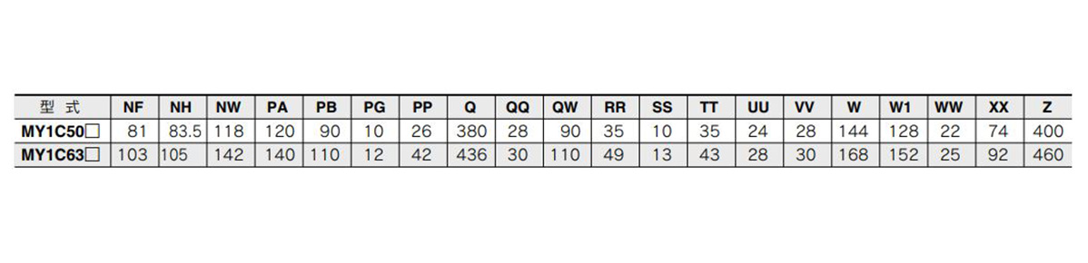
Dimension table image 2 of MY1C50□/MY1C5063□
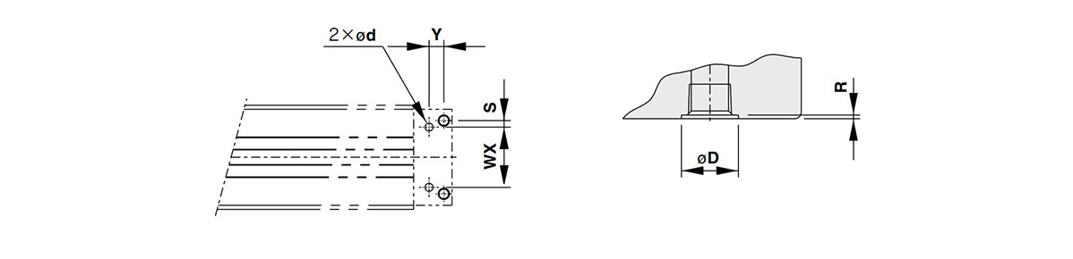
Piping hole dimensional drawing for centralized bottom piping of MY1C50□/MY1C5063□ (right: Bottom side (ZZ section) piping section (applicable O-ring)
(Units: mm)
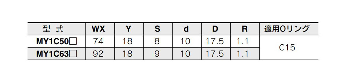
Image of piping hole dimension table for centralized bottom piping MY1C50□/MY1C5063□
* Please process the mounting surface with these dimensions.
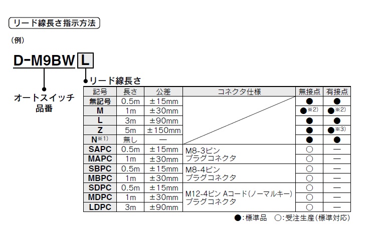
Please refer to the table below for details about lead wire / connector specifications.
Basic Information
| Type | Rodless Cylinder | Rodless Cylinder Joint Type | Mechanically Jointed |
|---|