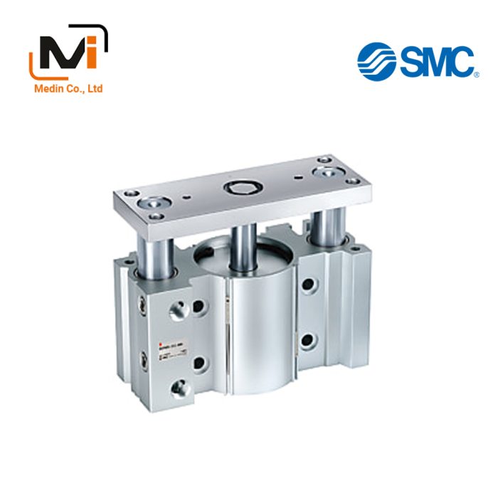
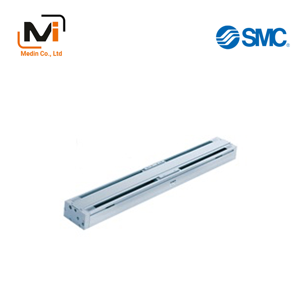
Magnetically Coupled Rodless Cylinder, Linear Guide Type CY1H Series
Product Description
A CY1H Series magnetically coupled rodless cylinder with linear guide manufactured by SMC.
[Features]
· A space-saving type cylinder with a magnetically coupled design that allows use in wide range of applications.
Download

Magnetically Coupled Rodless Cylinder, Linear Guide Type CY1H Series Specifications
Model Number Notation
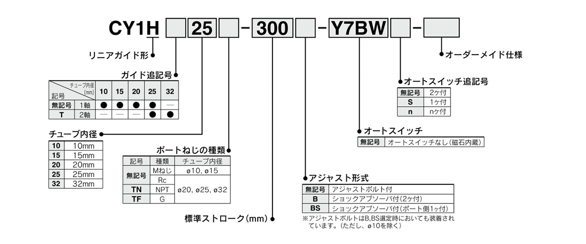
Model Number Notation
Shock Absorber Model Numbers
| Model | Type | Tube Internal Diameter (mm) | ||||
|---|---|---|---|---|---|---|
| 10 | 15 | 20 | 25 | 32 | ||
| CY1H | Standard (Shock Absorber RB Series) | RB0805 | RB0806 | RB1006 | RB1411 | – |
| Equipped with an RJ Series shock absorber / soft type (-XB22) | RJ0806H | RJ1007H | RJ1412H | – | ||
| CY1HT | Standard (Shock Absorber RB Series) | – | – | – | RB1411 | RB2015 |
| Equipped with an RJ Series shock absorber / soft type (-XB22) | – | – | – | RJ1412H | – | |
- *The lifespan of the shock absorber differs from that of the CY1H cylinder unit.
Specifications
| Tube Internal Diameter mm | 10 | 15 | 20 | 25 | 32 |
|---|---|---|---|---|---|
| Fluid | Air | ||||
| Operation Type | Double-acting type | ||||
| Maximum Operating Pressure | 0.7 MPa | ||||
| Minimum Operating Pressure | 0.2 MPa | ||||
| Guaranteed Proof Pressure | 1.05 MPa | ||||
| Ambient Temperature and Operating Fluid Temperature | -10°C to +60°C (no freezing) | ||||
| Piston Speed | 70 to 500 mm/s | ||||
| Cushioning (External Stopper) | Urethane bumper at both ends (standard), shock absorber (options) | ||||
| Lubrication | Not required (lubrication-free) | ||||
| Stroke Length Tolerance | 0 to 1.8 mm | ||||
| Holding Force (N) | 53.9 | 137 | 231 | 363 | 588 |
| Piping | Centralized piping type | ||||
| Piping connection port diameter | M5 × 0.8 | Rc 1/8 | |||
Standard Stroke Table
| Tube Inner Diameter (mm) | Number of Axes | Standard Stroke (mm) * | Maximum Manufacturable Stroke (mm) |
|---|---|---|---|
| 10 | 1 Axis | 100, 200, 300 | 500 |
| 15 | 100, 200, 300, 400, 500 | 750 | |
| 20 | 100, 200, 300, 400, 500, 600 | 1,000 | |
| 25 | 100, 200, 300, 400, 500, 600, 800 | 1,200 | |
| 25 | 2 Axis | 100, 200, 300, 400, 500, 600, 800, 1,000 | |
| 32 | 1,500 |
- *The stroke is manufacturable in 1 mm increments, up to the maximum stroke. However, for intermediate strokes other than the standard stroke, add the “-XB10” suffix to the model number. For those exceeding the standard stroke up to the maximum manufacturable stroke, add the “XB11” suffix to the model number.
Structural Drawing Examples
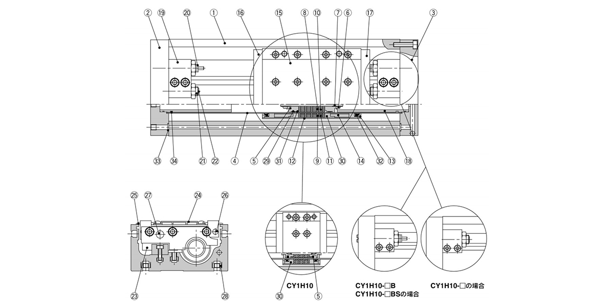
Single-axis type CY1H structural drawing
Component Parts
| Number | Part name | Material | Note |
|---|---|---|---|
| 1 | Rail base | Aluminum alloy | Anodized aluminum |
| 2 | Plate A | Aluminum alloy | Anodized |
| 3 | Plate B | Aluminum alloy | Anodized |
| 4 | Cylinder Tube | Stainless steel | – |
| 5 | Piston | Aluminum alloy | Chromate |
| 6 | Piston Nut | Carbon steel | Zinc chromate (Excluding CY1H10, 15) |
| 7 | Shaft | Stainless steel | – |
| 8 | Piston-Side Yoke | Rolled steel plate | Zinc chromate |
| 9 | External Slider Side Yoke | Rolled steel plate | Zinc chromate |
| 10 | Magnet A | – | – |
| 11 | Magnet B | – | – |
| 12 | External Slider Tube | Aluminum alloy | – |
| 13 | Spacer | Rolled steel plate | Nickel plating |
| 14 | Spaced Ring | Aluminum alloy | Chromate (excludes CY1H10) |
| 15 | Slide table | Aluminum alloy | Anodized |
| 16 | Side Plate A | Aluminum alloy | Anodized |
| 17 | Side Plate B | Aluminum alloy | Anodized |
| 18 | Internal Stopper | Aluminum alloy | Anodized |
| 19 | Stopper | Aluminum alloy | Anodized |
| 20 | Shock Absorber | – | RB Series |
| 21 | Adjustment Bolt | Chrome molybdenum steel | Nickel plating |
| 22 | Adjustment Bumper | Urethane rubber | – |
| 23 | Linear Guide | – | – |
| 24 | Top Cover | Aluminum alloy | Anodized |
| 25 | Dust Cover | Special resin | – |
| 26 | Magnet (for Auto Switches) | – | – |
| 27 | Parallel Pin | Carbon steel | Nickel plating |
| 28 | Square Nuts for Unit Mounting | Carbon steel | Nickel plating |
| *29 | Wear Ring A | Special resin | – |
| *30 | Wear Ring B | Special resin | – |
| *31 | Piston Seal | NBR | – |
| *32 | Scraper | NBR | – |
| *33 | O-ring | NBR | – |
| *34 | O-ring | NBR | – |
*There are 4 square nuts provided for mounting the main unit, regardless of the stroke.
Magnetically Coupled Rodless Cylinder, Linear Guide Type, CY1H Series, Example Dimensions
(Unit: mm)
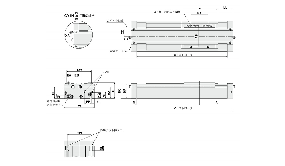
Single axis type / ø10 mm (internal diameter) dimensional drawing
| Model | A | EA | EB | H | HA | HB | HC | HG | HP | HT | J | L | LL | LW | M | MM | N | NL | NT |
|---|---|---|---|---|---|---|---|---|---|---|---|---|---|---|---|---|---|---|---|
| CY1H15 | 97 | 26.5 | 21 | 46 | 33.5 | 33.5 | 45 | 17 | 42 | 19 | M5 × 0.8 | 106 | 44 | 71.5 | M5 × 0.8 | 8 | 16.5 | 15 | 8 |
| CY1H20 | 102.5 | 26.5 | 22 | 54 | 42.5 | 41.5 | 53 | 16 | 50 | 23.5 | M5 × 0.8 | 108 | 48.5 | 75.5 | M5 × 0.8 | 8 | 18 | 15 | 8 |
| CY1H25 | 125 | 29 | 24 | 63 | 46 | 46 | 61.5 | 25 | 58.5 | 28 | M6 × 1.0 | 138 | 56 | 86 | M6 × 1.0 | 10 | 20.5 | 18 | 9 |
| Model | P | PA | PB | PP | S | TW | W | XA | XB | Z | ZZ |
|---|---|---|---|---|---|---|---|---|---|---|---|
| CY1H15 | M5 × 0.8 | 50 | 62 | 21 | 161 | 65 | 88.5 | – | – | 194 | 17.5 |
| CY1H20 | Rc 1/8 | 50 | 65 | 23 | 169 | 70 | 92.5 | – | – | 205 | 19.5 |
| CY1H25 | Rc 1/8 | 65 | 75 | 27 | 209 | 75 | 103 | 11.3 | 9.5 | 250 | 23.5 |
Usage Precautions
- *When within the allowable range, direct load can be applied. But when connecting with a load having a guide mechanism on the exterior, full center alignment work is required.
- *Guides are adjusted before shipping. Take care not to move the settings of the adjustment portion unintentionally.
- *Can be used without lubrication. If lubricating, use turbine oil class 1 (no additives) ISO VG32. (Machine oil and spindle oil cannot be used)
- *Avoid use in environments that may cause the degradation of cylinder sliding part lubricity. This includes environments where liquids such as water or machining fluids are dispersed within the cylinder, environments where water vapor is present or those environments where the adherence of contaminants or dust on the cylinder may be a concern.
- *Do not use if the magnet coupling has become unaligned or detached.
- *Never disassemble the magnet structure (piston slider, external slider).
Basic Information
| Type | Rodless Cylinder | Table Material | Aluminum Alloy | Rodless Cylinder Joint Type | Magnetic |
|---|---|---|---|---|---|
| Environment | General Purpose | Table Surface Treatment | Alumite | Piping Format | Centralized piping type |
| Specifications | Magnet built-in | Custom-made Specifications | 0.2 to 0.7 |