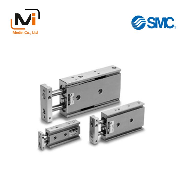

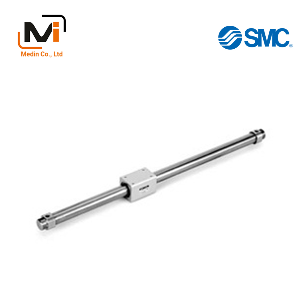
Magnetically Coupled Rodless Cylinder, Basic Type, CY3B Series
Product Description
The CY3B series is the basic type of the Magnetically Coupled Rodless Cylinder with improved bearing performance.
[Features]
· A good lubrication film is formed on the outer peripheral surface of the cylinder tube for improved durability.
· Reduced sliding resistance.
Download

Magnetically Coupled Rodless Cylinder, Basic Type, CY3B Series Details

Magnetically Coupled Rodless Cylinder, Basic Type, CY3B Series, product image
Magnetically Coupled Rodless Cylinder, Basic Type, CY3B Series Specifications
| Tube inner diameter (mm) | 6 | 10 | 15 | 20 | 25 | 32 | 40 | 50 | 63 |
|---|---|---|---|---|---|---|---|---|---|
| Usable fluids | Air | ||||||||
| Guaranteed pressure resistance | 1.05 MPa | ||||||||
| Maximum operating pressure | 0.7 MPa | ||||||||
| Minimum operating pressure | 0.16 | 0.16 | 0.16 | 0.16 | 0.15 | 0.14 | 0.12 | 0.12 | 0.12 |
| Ambient temperature and working fluid temperature | -10 to 60°C (however, no freezing) | ||||||||
| Operating piston speed | 50 to 500 mm/s | ||||||||
| Cushion | Rubber cushion | ||||||||
| Lubrication | Not required (lubrication-free) | ||||||||
| Allowable difference of stroke length (mm) | 0 to 250 st: (0 to +1.0), 251 to 1,000 st: (0 to +1.4), 1,001 st and above: (0 to +1.8) | ||||||||
| Mounting orientation | Horizontal, slanted, verticalNote) | ||||||||
| Mounting nuts (2 nuts) | Standard equipment (accessories) | ||||||||
| Magnetic retention force (N) | 19.6 | 53.9 | 137 | 231 | 363 | 588 | 922 | 1,471 | 2,256 |
Note: When mounting vertically, intermediate stopping using an air pressure circuit cannot be done.
Model number indication method
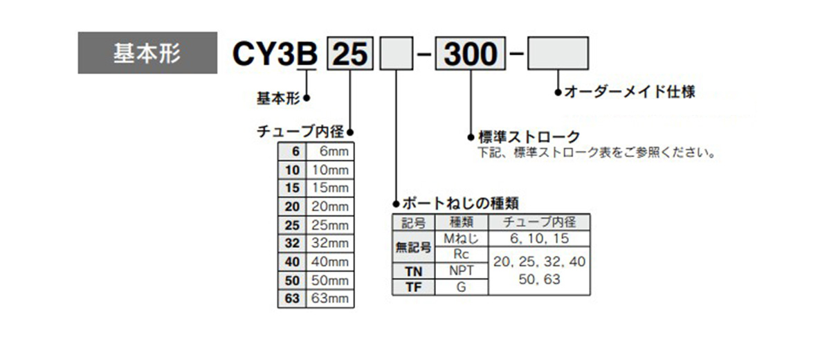
Model number example
Standard stroke table
| Tube inner diameter (mm) |
Standard stroke (mm) | Manufacturable Maximum stroke (mm) |
|---|---|---|
| 6 | 50, 100, 150 and 200 | 300 |
| 10 | 50, 100, 150, 200, 250 and 300 | 500 |
| 15 | 50, 100, 150, 200, 250, 300, 350 400, 450, 500 |
1,000 |
| 20 | 100, 150, 200, 250, 300, 350, 400, 450 500, 600, 700, 800 |
1,500 |
| 25 | 3,000 | |
| 32 | ||
| 40 | 100, 150, 200, 250, 300, 350, 400, 450 500, 600, 700, 800, 900, 1,000 |
3,000 |
| 50 | 5,000 | |
| 63 |
- *Long stroke type (XB11) when the stroke exceeds 2,000 st.
- *The longer the stroke, the larger the amount of deflection in the cylinder tube. Pay attention to the mounting bracket and clearance value.
- *Intermediate stroke can be adjusted in 1‑mm increments.
Structural Drawing
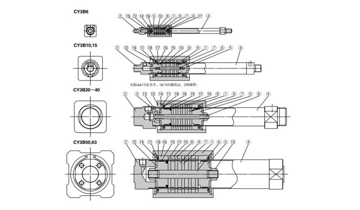
Magnetically Coupled Rodless Cylinder, Basic Type, CY3B Series, structural drawing
Components
| Number | Part name | Materials | Additional notes | ||
|---|---|---|---|---|---|
| 1 | Body | Aluminum alloy | Hard anodized aluminum | ||
| 2 | Head cover | ø6 (diameter 6 mm), ø10 (diameter 10 mm) | Brass | – | |
| ø15 (diameter 15 mm) to ø63 (diameter 63 mm) | Aluminum alloy | ||||
| 3 | End collar | Aluminum alloy | ø20 to 40 (diameter 20 to 40 mm) only | ||
| 4 | Cylinder tube | Stainless steel | – | ||
| 5 | Piston | ø6 (diameter 6 mm) | Brass | ø6 (diameter 6 mm) | Electroless Ni plating |
| ø10 to 63 (diameter 10 to 63 mm) | Aluminum alloy | ø10 to 63 (diameter 10 to 63 mm) | Chromate | ||
| 6 | Shaft | Stainless steel | – | ||
| 7 | Piston-side yoke | Rolled steel | Zinc chromate | ||
| 8 | External moving element side yoke | Rolled steel | Zinc chromate | ||
| 9 | Magnet A | – | – | ||
| 10 | Magnet B | – | – | ||
| 11 | Spacer | Aluminum alloy | No ø6 (diameter 6 mm) | ||
| 12 | Damper | Urethane rubber | – | ||
| 13 | Piston nut | Carbon steel | No ø6 to 15 (diameter 6 to 15 mm) | ||
| 14 | C-type retaining ring for hole | Carbon tool steel | Phosphate coated | ||
| 15 | Wear ring A | Special resin | – | ||
| 16 | Wear ring B | Special resin | – | ||
| 17 | Piston packing | NBR | – | ||
| 18 | Lub-retainer | Special resin | No ø6 (diameter 6 mm) | ||
| 19 | Cylinder tube gasket | NBR | ø6 (diameter 6 mm) and ø10 (diameter 10 mm) only | ||
Magnetically Coupled Rodless Cylinder, Basic Type, CY3B Series, example dimensions
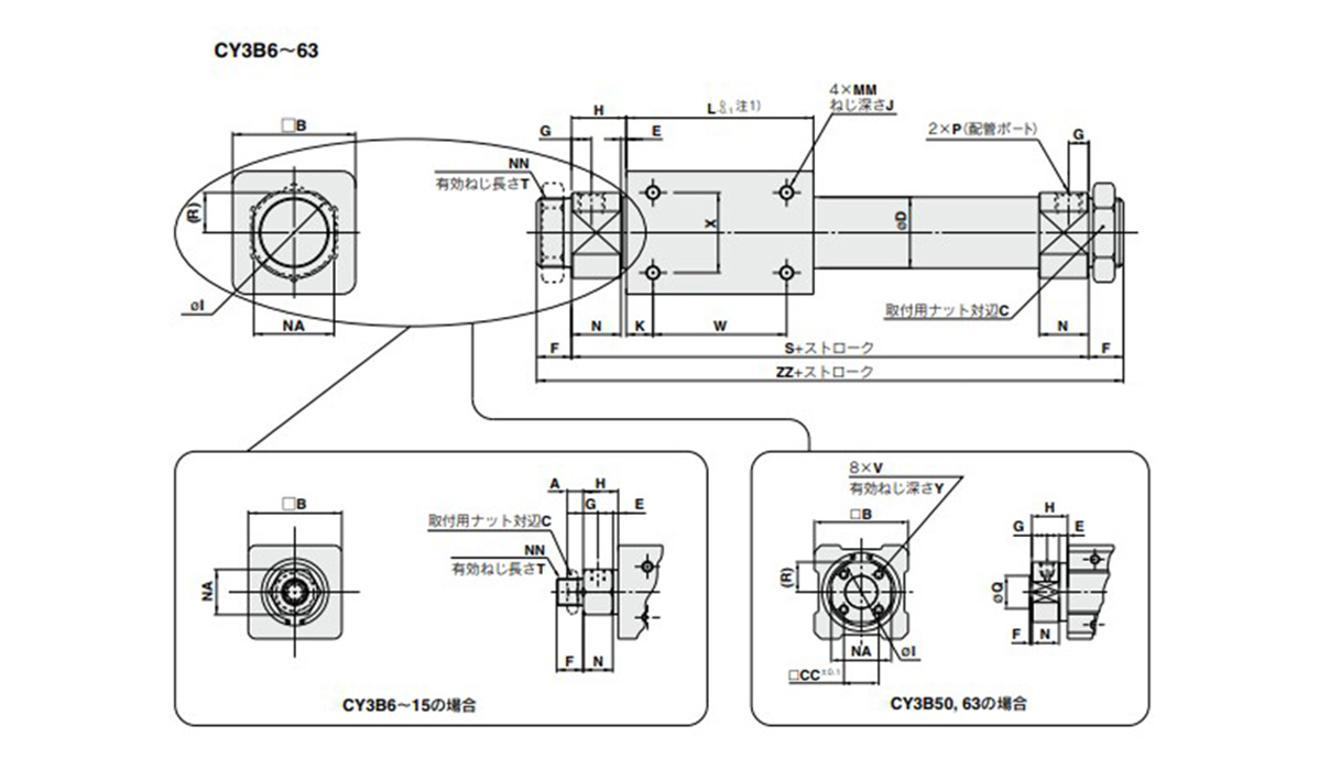
Basic type CY3B6 to CY3B63, dimensional drawing
Note 1: ø50 (diameter 50 mm) and ø63 (diameter 63 mm) are L (-0.2 to 0).
(Unit: mm)
| Model | A | B | C | CC | D | E | F | G | H | I | J | K | L |
|---|---|---|---|---|---|---|---|---|---|---|---|---|---|
| CY3B6 | 4 | 17 | 8* | – | 7.6 | 4 | 8* | 5 | 13.5* | – | 4.5 | 5 | 35 |
| CY3B10 | 4 | 25 | 14 | – | 12 | 1.5 | 9 | 5 | 12.5 | – | 4.5 | 4 | 38 |
| CY3B15 | 4 | 35 | 14 | – | 16.6* | 2 | 10 | 5.5 | 13 | – | 6 | 11 | 57 |
| CY3B20 | 8 | 36 | 26 | – | 21.6* | 2* | 13 | 7.5* | 20 | 28 | 6 | 8 | 66 |
| CY3B25 | 8 | 46 | 32 | – | 26.4* | 2* | 13 | 7.5* | 20.5 | 34 | 8 | 10 | 70 |
| CY3B32 | 8 | 60 | 32 | – | 33.6* | 2* | 16 | 8* | 22 | 40 | 8 | 15 | 80 |
| CY3B40 | 10 | 70 | 41 | – | 41.6* | 3* | 16 | 11 | 29 | 50 | 10 | 16 | 92 |
| CY3B50 | – | 86 | – | 32 | 52.4* | 8 | 2 | 14 | 33 | 58* | 12 | 25 | 110 |
| CY3B63 | – | 100 | – | 38 | 65.4* | 8 | 2 | 14 | 33 | 72* | 12 | 26 | 122 |
| Model | MM | N | NA | NN | Q | R | S | T | V |
|---|---|---|---|---|---|---|---|---|---|
| CY3B6 | M3 × 0.5 | 9.5* | 10* | M6 × 1* | – | – | 62* | 6.5 | – |
| CY3B10 | M3 × 0.5 | 11 | 14 | M10 × 1 | – | – | 63 | 7.5 | – |
| CY3B15 | M4 × 0.7 | 11 | 17 | M10 × 1 | – | – | 83 | 8 | – |
| CY3B20 | M4 × 0.7 | 18* | 24 | M20 × 1.5 | – | 12* | 106 | 10 | – |
| CY3B25 | M5 × 0.8 | 18.5* | 30 | M26 × 1.5 | – | 15* | 111 | 10 | – |
| CY3B32 | M6 × 1 | 20* | 36 | M26 × 1.5 | – | 18* | 124 | 13 | – |
| CY3B40 | M6 × 1 | 26* | 46 | M32 × 2 | – | 23* | 150 | 13 | – |
| CY3B50 | M8 × 1.25 | 25 | 55 | – | 30 (-0.037 to -0.007) | 27.5* | 176 | – | M8 × 1.25 |
| CY3B63 | M8 × 1.25 | 25 | 69 | – | 32 (-0.043 to -0.007) | 34.5* | 188 | – | M10 × 1.5 |
(Unit: mm)
| Model | W | X | Y | ZZ | P (piping port) | ||
|---|---|---|---|---|---|---|---|
| No mark | TN* | TF* | |||||
| CY3B6 | 25 | 10 | – | 78* | M3 × 0.5* | – | – |
| CY3B10 | 30 | 16 | – | 81 | M5 × 0.8 | – | – |
| CY3B15 | 35 | 19 | – | 103 | M5 × 0.8 | – | – |
| CY3B20 | 50 | 25 | – | 132 | Rc 1/8 | NPT1/8 | G1/8 |
| CY3B25 | 50 | 30 | – | 137 | Rc 1/8 | NPT1/8 | G1/8 |
| CY3B32 | 50 | 40 | – | 156 | Rc 1/8 | NPT1/8 | G1/8 |
| CY3B40 | 60 | 40 | – | 182 | Rc 1/4 | NPT1/4 | G1/4 |
| CY3B50 | 60 | 60 | 16 | 180 | Rc 1/4 | NPT1/4 | G1/4 |
| CY3B63 | 70 | 70 | 16 | 192 | Rc 1/4 | NPT1/4 | G1/4 |
Note 2: Dimensions marked with “*” are different from the CY1B series.
Note 3: Mounting nuts can be screwed on only for the effective thread length of the head cover (T dimension). When mounting a cylinder, consider the thickness of flange, etc.
Basic Information
| Type | Rodless Cylinder | Table Material | Aluminum Alloy | Rodless Cylinder Joint Type | Magnetic |
|---|---|---|---|---|---|
| Table Surface Treatment | Hard Anodize | Guide Type | Prototype | Cushion | Rubber cushion |