Electro-Pneumatic E-P HYREG VY1 Series
Product Description
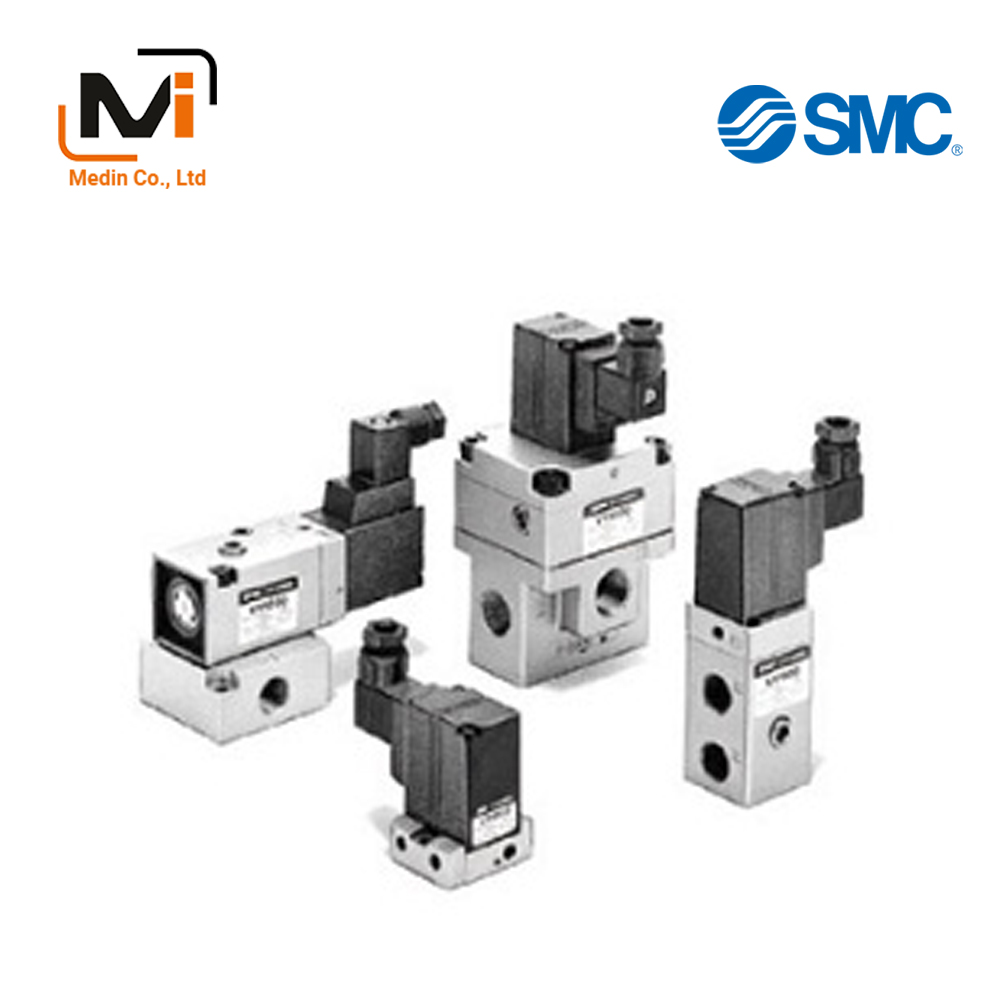
The Electro-Pneumatic E-P HYREG VY1 Series is a hybrid regulator combining a regulator and a solenoid valve.
[Features]
· Stepless controls via electric signals.
· Simple circuit configuration.
· Easy to handle.
· Manifold capable.
[Applications]
· Cylinder thrust control.
· Drive and thrust control.
· Flow control of various fluids / Pressure control of tanks / Air flow control for nozzles.
Download

Electro-Pneumatic E-P HYREG VY1 Series Details
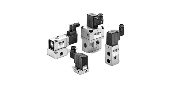
Electro-Pneumatic E-P HYREG VY1 Series: product image (1)
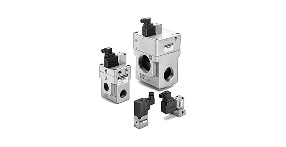
Electro-Pneumatic E-P HYREG VY1 Series: product image (2)
Electro-Pneumatic E-P HYREG VY1 Series Specification
Model number notation (standard specifications)
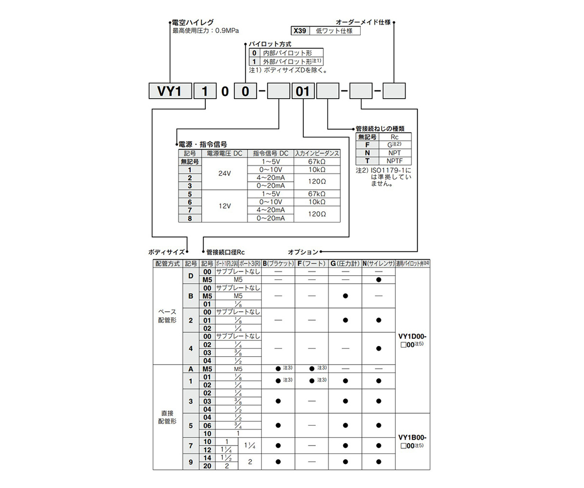
Standard specification, Model number example
- *Note 3) Only the bracket or foot can be mounted. They cannot be mounted together.
- *Note 4) When the pilot valve is replaced, it may not satisfy characteristics such as accuracy. As such, be sure to check that the product works without problems under the operating conditions before using. If the manufacturer is asked to repair the product, the manufacturer will perform an inspection to confirm the characteristics.
- *Note 5) The □ in the applicable pilot valve part number designates the power source / command signal.
- *Note 6) Cut off the command signal when pressure control on the secondary (outlet) side is not required, such as when the line is temporarily halted, etc.
Model Number Notation (Made-to-Order Specifications)
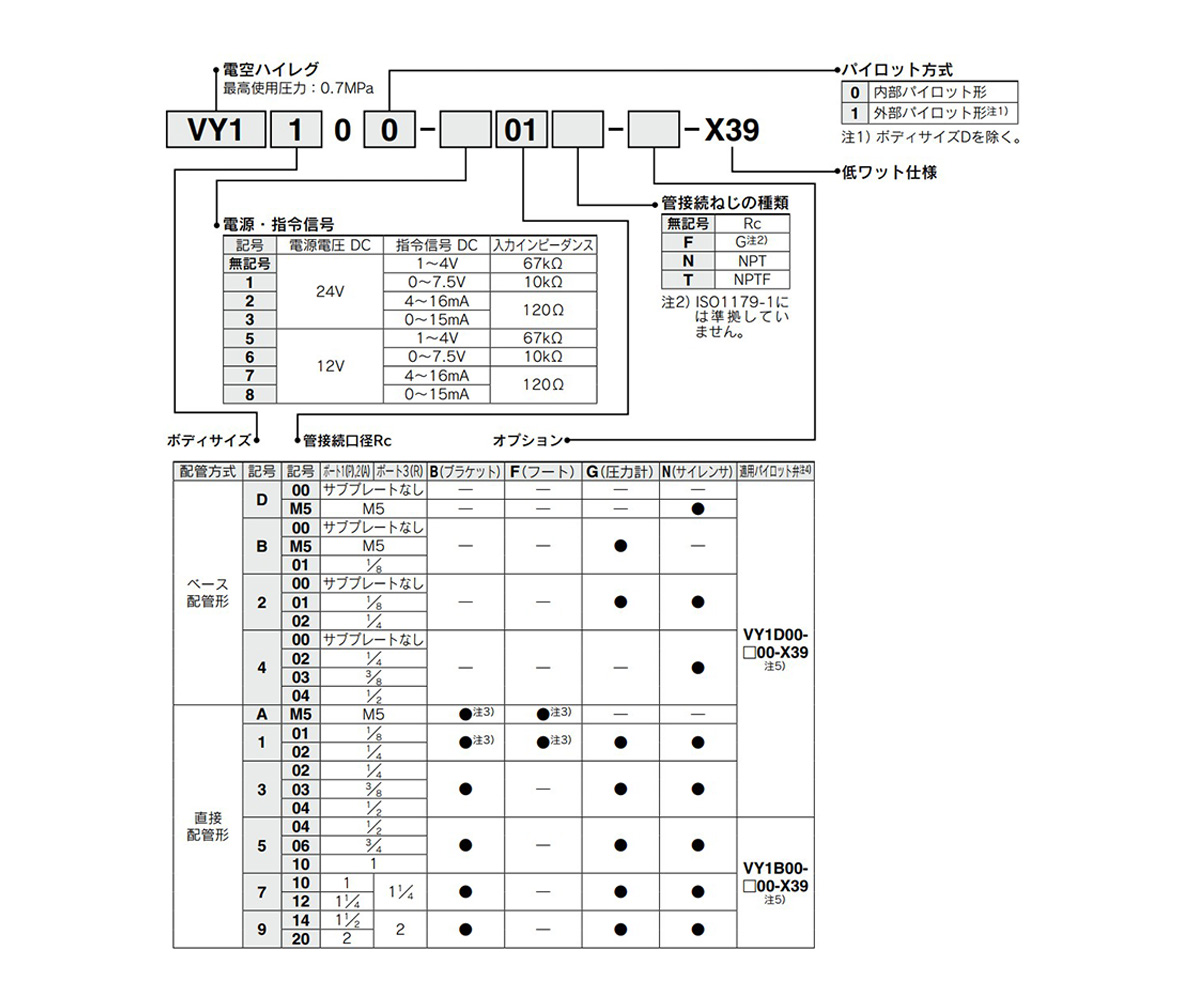
Made-to-order specifications: model number example
- *Note 3) Only the bracket or foot can be mounted. They cannot be mounted together.
- *Note 4) When the pilot valve is replaced, it may not satisfy characteristics such as accuracy. As such, be sure to check that the product works without problems under the operating conditions before using. If the manufacturer is asked to repair the product, the manufacturer will perform an inspection to confirm the characteristics.
- *Note 5) The □ in the applicable pilot valve part number designates the power source / command signal.
Standard (Standard Specification)
| Model | VY1D00 | VY1A0 (0 to 1) |
VY1B0 (0 to 1) |
VY110 (0 to 1) |
VY120 (0 to 1) |
VY130 (0 to 1) |
VY140 (0 to 1) |
VY150 (0 to 1) |
VY170 (0 to 1) |
VY190 (0 to 1) |
||||||||||||
|---|---|---|---|---|---|---|---|---|---|---|---|---|---|---|---|---|---|---|---|---|---|---|
| Piping connection port diameter | Port | M5 | M5 | M5 | 01 | 01 | 02 | 01 | 02 | 02 | 03 | 04 | 02 | 03 | 04 | 04 | 06 | 10 | 10 | 12 | 14 | 20 |
| 1(P) | M5 | M5 | M5 | 1/8 | 1/8 | 1/4 | 1/8 | 1/4 | 1/4 | 3/8 | 1/2 | 1/4 | 3/8 | 1/2 | 1/2 | 3/4 | 1 | 1 | 1 1/4 | 1 1/2 | 2 | |
| 2(A) | ||||||||||||||||||||||
| 3(R) | 1 1/4 | 2 | ||||||||||||||||||||
| Weight (kg) Note 1) | 0.11 | 0.16 | 0.19 | 0.25 | 0.35 | 0.55 | 0.75 | 1.5 | 2 | 4 | ||||||||||||
| Hysteresis Note 2) | 0.009 MPa | 0.023 MPa | 0.027 MPa | 0.045 MPa | ||||||||||||||||||
| Sensitivity Note 2) | 0.005 MPa | 0.009 MPa | 0.014 MPa | 0.018 MPa | ||||||||||||||||||
| Repeatability Note 2) | ±0.005 MPa | ±0.009 MPa | ±0.009 MPa | ±0.018 MPa | ||||||||||||||||||
| Response time Note 2) | 10 ms | 30 ms | ||||||||||||||||||||
| Applicable fluids | Air | |||||||||||||||||||||
| Ambient temperature and working fluid temperature | 0 to +50°C (no condensation) | |||||||||||||||||||||
| Maximum operating pressure | 0.9 MPa | |||||||||||||||||||||
| Set pressure range | 0.05 to 0.84 MPa (at supply pressure of 0.9 MPa) | |||||||||||||||||||||
| External pilot pressure | – (Direct operated) | Set pressure +0.04 MPa to 0.9 MPa (for VY1□01) | ||||||||||||||||||||
| Command signal Note 3) | 1 to 5 V DC, 0 to 10 V DC, 4 to 20 mA DC, 0 to 20 mA DC | |||||||||||||||||||||
| Power supply | 12 V DC ±10%, 24 V DC ±10%, 1.8 W or less | |||||||||||||||||||||
| Method of electrical entry of lead wire | DIN terminal | |||||||||||||||||||||
| Compatible cable | Cable outer diameter ø4 to 6.5 (outer diameter 4 to 6.5 mm) | |||||||||||||||||||||
| Bleed amount (pilot EXH port) | When not operating: zero, When operating: 10 L/min (ANR) (at supply pressure of 0.9 MPa) | |||||||||||||||||||||
| Installation orientation | Free | |||||||||||||||||||||
| Lubrication | Not required Note 4) | |||||||||||||||||||||
- *Note 1) The weight of the base piping type (sizes D, B, 2, 4) is indicated for specifications with a subplate.
- *Note 2) All values indicated for the characteristics are the maximum values.
- *Note 3) Cut off the command signal when pressure control on the secondary (outlet) side is not required, such as when the line is temporarily halted, etc.
- *Note 4) To lubricate the secondary (outlet) side of VY, use VY as an external pilot. Avoid lubrication to the pilot air.
- *Note 5) The non-lubricated specification is not applicable to these models.
- *Note 6) The service life is approximately 4,000 to 5,000 operating hours (when using AF + AFM).
This may be approx. 3,000 hours with ultra-dry air (dew point -40°C equivalent).
Specifications (Made-To-Order Specifications)
| Maximum operating pressure Note 6) | 0.7 MPa |
|---|---|
| Set pressure range | 0.05 to 0.66 MPa (at supply pressure of 0.7 MPa) |
| External pilot pressure | Set pressure +0.04 MPa to 0.7 MPa |
| Command signal Note 7) | 1 to 4 V DC, 0 to 7.5 V DC, 4 to 16 mA DC, 0 to 15 mA DC |
| Power supply | 12 V DC ±10%, 24 V DC ±10%, 0.8 W or less |
| Bleed amount (pilot EXH port) | When not operating: zero, When operating: 7 L/min (ANR) (at supply pressure of 0.7 MPa) |
- *Specifications other than those written below are the same as the standard specifications.
- *Note 6) Make sure the supply pressure stays below the maximum operating pressure.
Allowing the supply pressure to exceed the maximum operating pressure can cause abnormal leakage from the pressure valve and affect the set pressure. - *Note 7) Cut off the command signal when pressure control on the secondary (outlet) side is not required, such as when the line is temporarily halted, etc.
Structural Drawings
VY1A00/VY1A01, VY1B00/VY1B01 (Pilot Valve: VY1D00-□00)
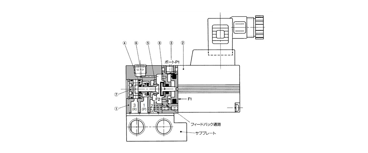
VY1A00/VY1A01, VY1B00/VY1B01 (Pilot Valve: VY1D00-□00): structural drawings
Component Parts
| Number | Part name | Materials |
|---|---|---|
| 1 | Body | Zinc alloy, cast |
| 2 | Pilot valve assembly | – |
| 3 | Pressure regulating piston | Aluminum alloy |
| 4 | Spring | Stainless steel |
| 5 | Valve guide | Stainless steel |
| 6 | Valve | Aluminum alloy / rubber |
| 7 | Retainer | Aluminum alloy |
| 8 | Rod | Stainless steel / rubber |
VY1100/VY1101, VY1200/VY1201, VY1300/VY1301, VY1400/VY1401 (Pilot Valve: VY1D00-□00), (Pilot Valve: VY1B00-□00), VY1500/VY1501, VY1700/VY1701, VY1900/VY1901
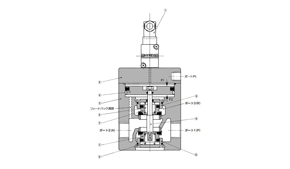
VY1100/VY1101, VY1200/VY1201, VY1300/VY1301, VY1400/VY1401 (Pilot valve: VY1D00-□00), (Pilot Valve: VY1B00-□00), VY1500/VY1501, VY1700/VY1701, VY1900/VY1901: structural drawings
Component Parts
| Number | Part name | Materials |
|---|---|---|
| 1 | Pilot valve assembly | – |
| 2 | Body | Aluminum alloy, cast |
| 3 | Cover | Aluminum alloy, cast |
| 4 | Pressure regulating piston | Aluminum alloy |
| 5 | Spring | Stainless steel |
| 6 | Valve guide | Aluminum alloy |
| 7 | Poppet valve | Aluminum alloy / rubber |
| 8 | Shaft | Stainless steel |
| 9 | Valve guide | Aluminum alloy |
Electro-Pneumatic E-P HYREG VY1 Series: Dimensions Examples
(Unit: mm)
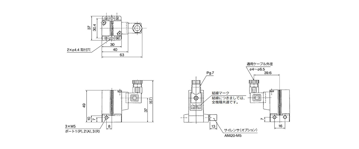
VY1D00 dimensional drawing
Basic Information
| Regulator, Pressure Boosting Valve | Regulator | Regulator Type | Electropneumatic | Applicable Fluid | Air |
|---|---|---|---|---|---|
| Shape | Standard | Operating Environment | Standard | Adverse Current Function | No |