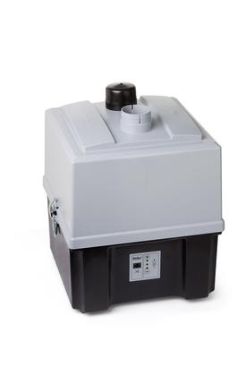
Booster Regulator VBA Series
Product Description
The Booster Regulator VBA Series features air-only operation, so no electricity is needed. Furthermore, it is also easy-to-install and also generates only low amounts of heat.
[Features]
· Floating piston structure.
· Metal noise reduced by the implementation of a damper on the impact part of the switching valve.
· The high noise-reduction silencer reduces exhaust noise.
· Features a built-in mesh filter at the IN port, preventing operation failure due to contamination by foreign matter.
· The air-feeding tube is integrated with the main tube, mitigating condensation caused by cooling during exhaust expansion.
· Standard fittings can be used, enabling remote pressure monitoring, etc.
Download

Booster Regulator VBA Series Details

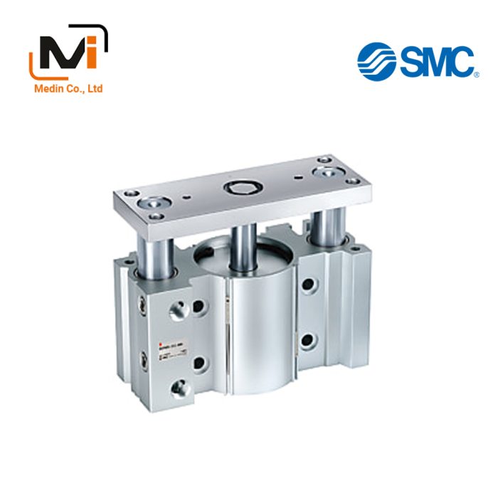
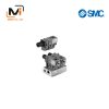
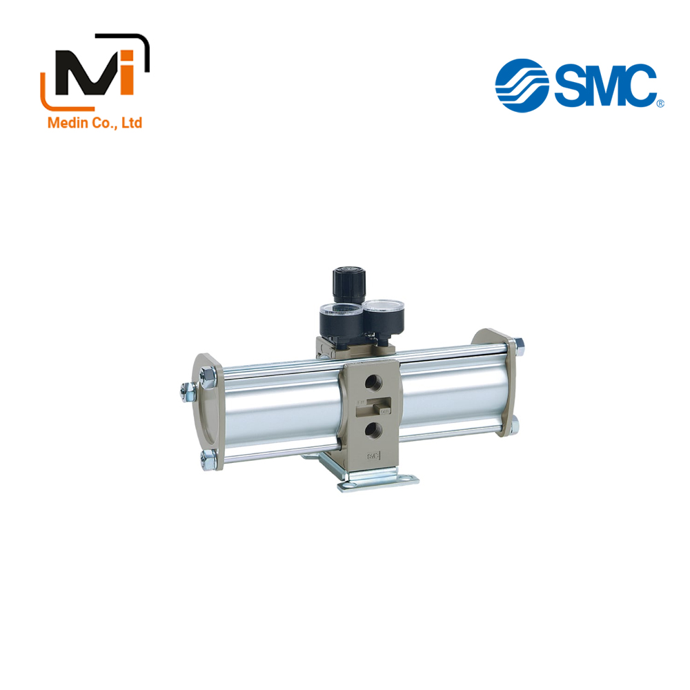
Booster Regulator VBA Series: product images
Booster Regulator VBA Series Specifications
Model Number Notation
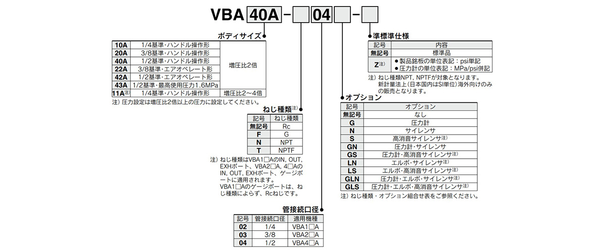
Model number notation: images
Thread Type / Option Combinations Table
| Body size | Screw Type | Option | Semi-standard specifications | ||||||||||
|---|---|---|---|---|---|---|---|---|---|---|---|---|---|
| No symbol | G | N | S | GN | GS | LN | LS | GLN | GLS | No symbol | -Z | ||
| 10A 11A |
No symbol | ● | ● | ● | ● | ● | ● | ● | ● | ● | ● | ● | – |
| F | ● | ● | ● | ● | ● | ● | ● | ● | ● | ● | ● | – | |
| N | ● | ● | ● | – | ● | – | ● | – | ● | – | ● | ● | |
| T | ● | ● | ● | – | ● | – | ● | – | ● | – | ● | ● | |
| 20A 22A |
No symbol | ● | ● | ● | ● | ● | ● | – | ● | – | |||
| F | ● | ● | ● | ● | ● | ● | ● | – | |||||
| N | ● | ● | ● | ● | ● | ● | ● | ● | |||||
| T | ● | ● | ● | ● | ● | ● | ● | ● | |||||
| 40A 42A 43A |
No symbol | ● | ● | ● | ● | ● | ● | – | ● | – | |||
| F | ● | ● | ● | ● | ● | ● | ● | – | |||||
| N | ● | ● | ● | ● | ● | ● | ● | ● | |||||
| T | ● | ● | ● | ● | ● | ● | ● | ● | |||||
Specifications Table
| Model | VBA10A-02 | VBA20A-03 | VBA40A-04 | VBA22A-03 | VBA42A-04 | VBA43A-04 | VBA11A-02 |
|---|---|---|---|---|---|---|---|
| Applicable fluids | Compressed air | ||||||
| Pressure increase ratio | 2 times | 2 to 4 times Note 4) | |||||
| Pressure adjustment mechanism | Handle-operated type with relief function Note 2) |
Air-operated type | Handle-operated type with relief function Note 2) |
||||
| Maximum flow rate Note 3) L/min (ANR) | 230 | 1,000 | 1,900 | 1,000 | 1,900 | 1,600 | 70 |
| Set pressure range: MPa | 0.2 to 2.0 | 0.2 to 1.0 | 0.2 to 1.0 | 0.2 to 1.6 | 0.2 to 2.0 | ||
| Supply pressure range – MPa | 0.1 to 1.0 | ||||||
| Proof pressure – MPa | 3 | 1.5 | 2.4 | 3 | |||
| Connection port size (IN, OUT, EXH 3 locations) – Rc |
1/4 | 3/8 | 1/2 | 3/8 | 1/2 | 1/4 | |
| Pressure gauge connection port size (IN, OUT 2 locations) – Rc |
1/8 | ||||||
| Tank connection port (with plug) Note 5) | 1/4 | 3/8 | 1/2 | 3/8 | 1/2 | 1/4 | |
| Ambient and working fluid temperature °C | 2 to 50 (no freezing) | ||||||
| Installation orientation | Horizontal | ||||||
| Lubrication | Grease (non-lube) | ||||||
| Weight – kg | 0.84 | 3.9 | 8.6 | 3.9 | 8.6 | 8.6 | 0.89 |
Note 2) If the OUT pressure is higher than the set pressure for the handle, excess pressure will be exhausted from the back of the handle.
Note 3) Flow rate at IN = OUT = 0.5 MPa. The pressure varies according to the operating conditions.
Note 4) Configure the pressure so that it is at least double the pressure increase ratio.
Note 5) The tank connection port cannot be used for purposes other than connection with VBAT.