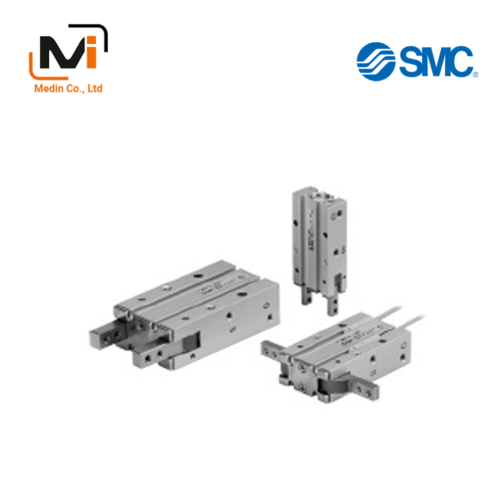
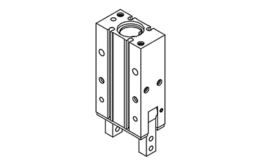
180° Angular Type Air Gripper MHY2 Series
Product Description
[Features]
· Light and compact series in small bore sizes.
· Improved mounting repeatability.
· Can be equipped with auto switches in 4 locations.
· The reduced opening sizes help prevent contaminants from getting inside.
· Uses stainless steel as standard.
Download

180° Angular Type Air Chuck MHY2 Series Specifications
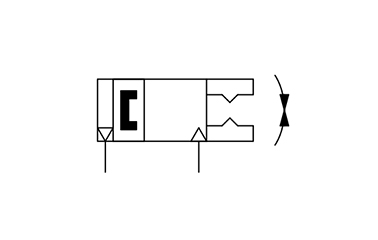
MHY2 Series JIS symbol (double acting, external gripping)

Finger option: standard tapped mounting external appearance
Finger option: through-holes in opening/closing direction external appearance
| Applicable fluids | Air |
|---|---|
| Operating pressure | 0.1 to 0.6 MPa |
| Ambient temperature and working fluid temperature | -10 to +60°C |
| Repeat accuracy | ±0.2 mm |
| Maximum operating frequency | 60 c.p.m |
| Lubrication | Non-lube |
| Operating method | Double acting |
| Auto switch (option)* | Solid state auto switch (3-wire, 2-wire) |
Note) See the manufacturer’s catalog for detailed specifications of auto switches.
Model
| Model | Cylinder inner diameter (mm) | Gripping moment (effective value) N·mNote 1) | Opening/closing angle (both sides) | Weight (g) Note 2) | |
|---|---|---|---|---|---|
| Opening side | Closing side | ||||
| MHY2-10D | 10 | 0.16 | 180 ° | -3 ° | 70 |
| MHY2-16D | 16 | 0.54 | 150 | ||
| MHY2-20D | 20 | 1.10 | 320 | ||
| MHY2-25D | 25 | 2.28 | 560 | ||
Note 1) Value at a pressure of 0.5 MPa.
Note 2) Values do not include auto switch weight.
Outline dimensional drawing
(Unit: mm)
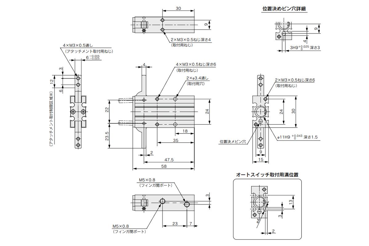
MHY2-10D dimensional drawing: (top right) pin hole positioning dimensional drawing / (bottom right) auto switch mounting groove dimensional drawing
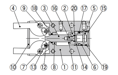
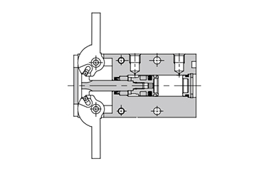
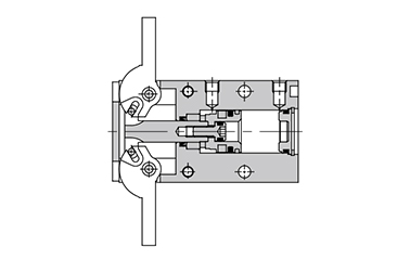
Structural drawing
Fingers closed
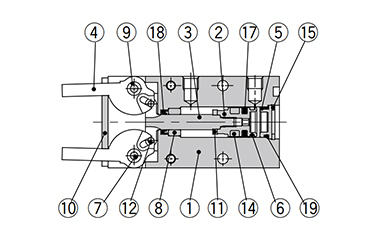
ø10 (cylinder inner diameter 10 mm) structure drawing
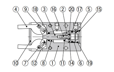
ø16 (cylinder inner diameter 16 mm) structure drawing
ø20 (cylinder inner diameter 20 mm), ø25 (cylinder inner diameter 25 mm) structure drawing
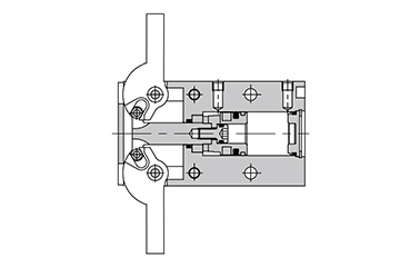
Fingers open
ø10 (cylinder inner diameter 10 mm) structure drawing
ø16 (cylinder inner diameter 16 mm) structure drawing
ø20 (cylinder inner diameter 20 mm), ø25 (cylinder inner diameter 25 mm) structure drawing
Component parts
| Number | Part name | Material | Note |
|---|---|---|---|
| 1 | Body | Aluminum Alloy | Hard anodizing |
| 2 | Piston | ø10 (diameter 10 mm): stainless steel ø16 to 25 (diameter 16 to 25 mm): aluminum alloy |
ø16 to 25 (diameter 16 to 25 mm): chromate treatment |
| 3 | Joint | Stainless steel | Heat treated |
| 4 | Finger | Stainless steel | Heat treated |
| 5 | Cap | Resin | – |
| 6 | Wear ring | Resin | – |
| 7 | Shaft | Stainless steel | Nitrided |
| 8 | Bushing A | Sintered alloy steel | – |
| 9 | Bushing B | Sintered alloy steel | – |
| 10 | End plate | Stainless steel | – |
| 11 | Dampers | Urethane rubber | – |
| 12 | Needle roller | High carbon chrome bearing steel | – |
| 13 | Joint roller | Carbon steel | Nitrided |
| 14 | Rubber magnet | Synthetic rubber | – |
| 15 | Type C retaining ring | Carbon steel | Phosphate coated |
| 16 | Piston bolt | Stainless steel | – |
| 17 | Piston Gasket | NBR | – |
| 18 | Rod Gasket | NBR | – |
| 19 | Gasket | NBR | – |
| 20 | Gasket | NBR | – |
Precautions
- *See the manufacturer’s catalog for the selection procedure, effective gripping force and allowable overhang amount.
- *See the manufacturer’s catalog for product information other than the above.
Basic Information
| Type | Main body | Gripping Methods | Pinch, Swing Type | Number of Fingers | 2 pcs. |
|---|---|---|---|---|---|
| Main Body Shape | Square Shape | Operation Method | Double Acting Type | Finger Closing Angle A2(deg) | -3 |
| Additional Functions | Not Provided | Stroke Adjustment Mechanism | Not Provided |