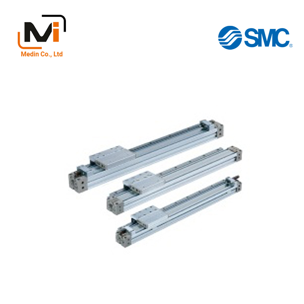
Xi Lanh Khí Nén SMC MY1H Series MY1H25 MY1H32 MY1H40
Mechanically Jointed Rodless Cylinder, Linear Guide Type, MY1H-Z Series
With the MY1H-Z series, piping is possible from the 4 directions of the head cover.
Download

Xi Lanh Khí Nén SMC MY1H Series MY1H25 MY1H32 MY1H40v
Mechanically Jointed Rodless Cylinder, Linear Guide Type, MY1H-Z Series Specifications – Xi Lanh Khí Nén SMC
[Features] · Piping on site is adjustable depending on the state of the installation.· Adjusting the cushion needle is easy.
Model Indication Method
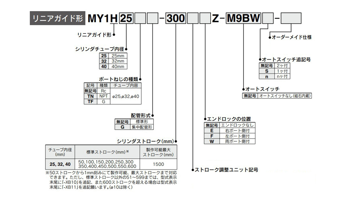
Model indication method, image
Compatible auto switches
| Type | Special function | Lead wire outlet | Indicator light | Wiring (output) | Load voltage | Auto switch part number | Lead wire length (m) | Pre-wired connector | Compatible load | ||||||||
|---|---|---|---|---|---|---|---|---|---|---|---|---|---|---|---|---|---|
| DC | AC | Vertical outlet | Lateral outlet | 0.5 (no mark) |
1 (M) |
3 (L) |
5 (Z) |
None (N) |
|||||||||
| Non-contact auto switch | – | Grommet | Available | 3-wire (NPN) | 24 V | 5 V, 12 V | – | M9NV | M9N | ● | ● | ● | ○ | ○ | ○ | IC circuit | Relay, PLC |
| 3-wire (PNP) | M9PV | M9P | ● | ● | ● | ○ | ○ | ○ | |||||||||
| 2-wire | 12 V | M9BV | M9B | ● | ● | ● | ○ | ○ | ○ | – | |||||||
| Diagnostic display (2-color display) | 3-wire (NPN) | 5 V, 12 V | M9NWV | M9NW | ● | ● | ● | ○ | ○ | ○ | IC circuit | ||||||
| 3-wire (PNP) | M9PWV | M9PW | ● | ● | ● | ○ | ○ | ○ | |||||||||
| 2-wire | 12 V | M9BWV | M9BW | ● | ● | ● | ○ | ○ | ○ | – | |||||||
| Part with enhanced water resistance (2-color display) | 3-wire (NPN) | 5 V, 12 V | Note 1M9NAV | Note 1M9NA | ○ | ○ | ● | ○ | – | ○ | IC circuit | ||||||
| 3-wire (PNP) | Note 1M9PAV | Note 1M9PA | ○ | ○ | ● | ○ | – | ○ | |||||||||
| 2-wire | 12 V | Note 1M9BAV | Note 1M9BA | ○ | ○ | ● | ○ | – | ○ | – | |||||||
| Contact auto switch | – | Grommet | Available | 3-wire (NPN equivalent) | – | 5 V | – | A96V | A96 | ● | – | ● | – | – | – | IC circuit | – |
| 2-wire | 24 V | 12 V | 100 V | Note 2A93V | A93 | ● | ● | ● | ● | – | – | – | Relay, PLC | ||||
| NA | 100 V or less | A90V | A90 | ● | – | ● | – | – | – | IC circuit | |||||||
- Note 1 Auto switches with enhanced water resistance can be mounted on the above model products, but that does not guarantee the water-resistant performance of the product.
Confirm with the manufacturer for regarding the above models with enhanced water resistance. - Note 2 The type with a 1 m lead wire only supports D-A93.
Specifications chart
| Tube inner diameter (mm) | 25 | 32 | 40 | |
|---|---|---|---|---|
| Usable fluids | Air | |||
| Operating type | Double-acting type | |||
| Operating pressure range | 0.1 to 0.8 MPa | |||
| Guaranteed pressure resistance | 1.2 MPa | |||
| Ambient temperature and working fluid temperature | 5 to 60°C | |||
| Cushion | Air cushion | |||
| Lubrication | Lubrication-free | |||
| Allowable difference of stroke length | 0 to +1.8 | |||
| Piping connection port diameter | Front/side port | Rc 1/8 | Rc 1/4 | |
| Bottom port | ø6 (diameter 6 mm) | ø8 (diameter 8 mm) | ||
Made-to-order specifications
| Display symbol | Specifications/details |
|---|---|
| -X168 | Helical coil insert screw specifications |
Made-to-order specifications
| Display symbol | Specifications/details |
|---|---|
| -XB10 | Intermediate stroke (dedicated body used) |
| -XB11 | Long stroke type |
| -XB22 | Shock absorber / soft type RJ series-equipped |
| -XC56 | Includes dowel pins |
Lock specifications
| Tube inner diameter (mm) | 25 | 32 | 40 |
|---|---|---|---|
| Lock position | One side (selectable), both sides | ||
| Retention (MAX.) N | 270 | 450 | 700 |
| Stroke adjustable range (mm) | 0 to -11.5 | 0 to -12 | 0 to -16 |
| Backlash | 1 mm or less | ||
| Manual unlock | Allowable (non-locking type) | ||
Operating piston speed
| Tube inner diameter (mm) | 25 to 40 | |
|---|---|---|
| No stroke adjustment unit | 100 to 1,000 mm/s | |
| Stroke adjustment unit |
A unit | 100 to 1,000 mm/sNote 1) |
| L unit, H unit | 100 to 1,500 mm/sNote 2) | |
Note 1: Air cushioning performance is reduced when the adjusting bolt is used to increase the stroke adjustment. Meanwhile, in ranges exceeding the air cushion stroke, the working piston speed will become 100 to 200 mm/s.
Note 2: The working piston speed will become 100 to 1,000 mm/s when using centralized piping.
Note 3: Use at a speed within the range of the absorption capacity.
Stroke adjustment unit specifications
| Tube inner diameter (mm) | 25 | 32 | 40 | |||||||
|---|---|---|---|---|---|---|---|---|---|---|
| Unit symbol | A | L | H | A | L | H | A | L | H | |
| Configuration details Shock absorber model |
Adjusting bolt included |
RB 1007 + Adjusting bolt included |
RB 1412 + Adjusting bolt included |
Adjusting bolt included |
RB 1412 + Adjusting bolt included |
RB 2015 + Adjusting bolt included |
Adjusting bolt included |
RB 1412 + Adjusting bolt included |
RB 2015 + Adjusting bolt included |
|
| Stroke adjustment range of each spacer for intermediate fixing (mm) | No spacer | 0 to -11.5 | 0 to -12 | 0 to -16 | ||||||
| With short spacer | -11.5 to -23 | -12 to -24 | -16 to -32 | |||||||
| With long spacer | -23 to -34.5 | -24 to -36 | -32 to -48 | |||||||
- *The stroke adjustment range is the adjustment range of one side when attached to a cylinder.
Stroke adjustment unit symbol
| – | Right stroke adjustment unit | |||||||||||
|---|---|---|---|---|---|---|---|---|---|---|---|---|
| No unit | A: Adjusting bolt included | L: Shock absorber for low loads and adjusting bolt included | H: Shock absorber for high loads and adjusting bolt included | |||||||||
| – | With short spacer |
With long spacer |
– | With short spacer |
With long spacer |
– | With short spacer |
With long spacer |
||||
| Left side stroke adjustment unit | No unit | No mark | SA | SA6 | SA7 | SL | SL6 | SL7 | SH | SH6 | SH7 | |
| A: Adjusting bolt included | – | AS | A | AA6 | AA7 | AL | AL6 | AL7 | AH | AH6 | AH7 | |
| With short spacer | A6S | A6A | A6 | A6A7 | A6L | A6L6 | A6L7 | A6H | A6H6 | A6H7 | ||
| With long spacer | A7S | A7A | A7A6 | A7 | A7L | A7L6 | A7L7 | A7H | A7H6 | A7H7 | ||
| L: Shock absorber for low loads and adjusting bolt included |
– | LS | LA | LA6 | LA7 | L | LL6 | LL7 | LH | LH6 | LH7 | |
| With short spacer | L6S | L6A | L6A6 | L6A7 | L6L | L6 | L6L7 | L6H | L6H6 | L6H7 | ||
| With long spacer | L7S | L7A | L7A6 | L7A7 | L7L | L7L6 | L7 | L7H | L7H6 | L7H7 | ||
| H: Shock absorber for high loads and adjusting bolt included |
– | HS | HA | HA6 | HA7 | HL | HL6 | HL7 | H | HH6 | HH7 | |
| With short spacer | H6S | H6A | H6A6 | H6A7 | H6L | H6L6 | H6L7 | H6H | H6 | H6H7 | ||
| With long spacer | H7S | H7A | H7A6 | H7A7 | H7L | H7L6 | H7L7 | H7H | H7H6 | H7 | ||
- *The spacer for intermediate fixing of the stroke adjustment unit cannot be used on the side to when the end lock is attached.
- *The spacer is a mounting bracket for fixing the stroke adjustment unit in an intermediate position of the stroke.
The model number of the shock absorber for the L and H units
| Type | Stroke adjustment unit |
Tube inner diameter (mm) | ||
|---|---|---|---|---|
| 25 | 32 | 40 | ||
| Standard (shock absorber RB series) | L | RB1007 | RB1412 | |
| H | RB1412 | RB2015 | ||
| Shock absorber / soft type RJ series-equipped (-XB22) |
L | RJ1007H | RJ1412H | |
| H | RJ1412H | – | – | |
- *The lifespan of the shock absorber is different from that of the MY1H cylinder main body.
- *The shock absorber / soft type RJ series-equipped (-XB22) has made-to-order specifications.
Shock absorber specifications
| Model | RB 1007 |
RB 1412 |
RB 2015 |
|
|---|---|---|---|---|
| Maximum energy absorption (J) | 5.9 | 19.6 | 58.8 | |
| Stroke absorption (mm) | 7 | 12 | 15 | |
| Maximum collision velocity (mm/s) | 1,500 | 1,500 | 1,500 | |
| Maximum operating frequency (cycle/min) | 70 | 45 | 25 | |
| Spring force (N) | When expanded | 4.22 | 6.86 | 8.34 |
| When compressed | 6.86 | 15.98 | 20.50 | |
| Operating temperature range (°C) | 5 to 60 | |||
- *The lifespan of the shock absorber will differ from that of the MY1H cylinder main body depending on the use conditions.
Standard type, structural drawing
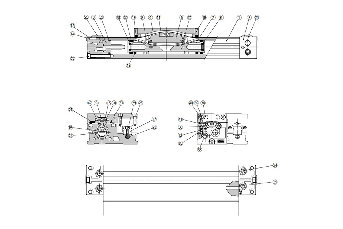
Standard type, structural drawing
Components
| Number | Description | Materials | Additional notes |
|---|---|---|---|
| 1 | Cylinder tube | Aluminum alloy | Hard anodized aluminum |
| 2 | Head cover | Aluminum alloy | Painted |
| 3 | Cushion boss | Special resin | – |
| 4 | Slide table | Aluminum alloy | Hard anodized aluminum |
| 5 | Piston yoke | Aluminum alloy | Chromate |
| 6 | Piston | Aluminum alloy | Chromate |
| 7 | Wear ring | Special resin | – |
| 8 | Belt separator | Special resin | – |
| 9 | Guide roller | Special resin | – |
| 10 | Parallel pin | Stainless steel | – |
| 11 | Coupler | Ferrous sintered material | – |
| 12 | Head plate | Stainless steel | – |
| 13 | Cushion needle | Rolled steel | Nickel plating |
| 14 | Belt clamp | Special resin | – |
| 17 | Guide | – | – |
| 18 | End cover | Special resin | – |
| 20 | Steel ball | Carbon tool steel | – |
| 21 | Bearing | Special resin | – |
| 22 | Magnet | Rare earth magnet | – |
| 23 | Square nut | Carbon steel | Chromate |
| 24 | Spring pin | Bearing steel | – |
| 26 | Thin-head screw | Chrome molybdenum steel | Chromate |
| 27 | Hex socket head bolt | Chrome molybdenum steel | Chromate |
| 28 | Hex socket head bolt | Chrome molybdenum steel | Chromate |
| 29 | Hex socket head bolt | Chrome molybdenum steel | Chromate |
| 33 | Hex socket head taper plug (tapered) | Carbon steel | Chromate (in the case of centralized piping: 10 pcs.) |
| 34 | Hex socket head taper plug (tapered) | Carbon steel | Chromate (in the case of centralized piping: 4 pcs.) |
| 38 | Stopper | Carbon steel | – |
| 39 | Spacer | Stainless steel | – |
| 40 | Hex socket head cap button screw | Chrome molybdenum steel | Chromate |
| 41 | CR-type retaining ring | Steel for springs | – |
| 42 | Seal magnet | Rubber magnet | – |
| 43 | Lub-retainer | Special resin | – |
Replacement parts / seal kit
| Number | Description | Materials | Quantity | MY1H25 | MY1H32 | MY1H40 |
|---|---|---|---|---|---|---|
| 15 | Seal belt | Urethane | 1 | MY25-16C-[stroke] | MY32-16C-[stroke] | MY40-16C-[stroke] |
| 16 | Dust seal band | Stainless steel | 1 | MY1B25-16B-[stroke] | MY1B32-16B-[stroke] | MY1B40-16B-[stroke] |
| 25 | Cushion boss gasket | NBR | 2 | MYB25-16GA5900 | MYB32-16GA5901 | MYB40-16GA5902 |
| 36 | O-ring | NBR | 2 | KA00311 | KA00320 | KA00320 |
| (ø5.1 (diameter 5.1 mm) × ø3 (diameter 3 mm × ø1.05 (diameter 1.05 mm)) | (ø7.15 (diameter 7.15 mm) × ø3.75 (diameter 3.75 mm) × ø1.7 (diameter 1.7 mm)) | (ø7.15 (diameter 7.15 mm) × ø3.75 (diameter 3.75 mm) × ø1.7 (diameter 1.7 mm)) | ||||
| 37 | Side scraper | Special resin | 2 | MYH25-15BK2902B | MYH32-15BK2903B | MYH40-15BK2904B |
| 19 | Scraper | NBR | 2 | MY1H25-PS | MY1H32-PS | MY1H40-PS |
| 30 | Piston packing | NBR | 2 | |||
| 31 | Cushion seal | NBR | 2 | |||
| 32 | Tube gasket | NBR | 2 | |||
| 35 | O-ring | NBR | 2 |
- *Because the seal kit includes 19, 30, 31, 32, and 35, order using the order number of each tube inner diameter.
- *The seal kit includes a grease pack (10 g).
A grease pack (20 g) is included when 15 or 16 are shipped as single items.
End lock structural drawing
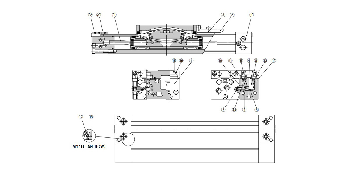
End lock structural drawing
Components
| Number | Description | Materials | Additional notes |
|---|---|---|---|
| 1 | Body for locking | Aluminum alloy | Painted |
| 2 | Lock finger | Carbon steel | Nickel plating after quenching |
| 3 | Lock finger fixture | Rolled steel | Nickel plating |
| 4 | Lock piston | Carbon tool steel material | Kanizen plating after quenching |
| 5 | Rod cover | Aluminum alloy | Hard anodized aluminum |
| 6 | Return spring | Spring steel | Zinc chromate |
| 7 | Bypass pipe | Aluminum alloy | Hard anodized aluminum |
| 10 | Steel ball | High-carbon chromium bearing steel | – |
| 11 | Steel ball | High-carbon chromium bearing steel | – |
| 13 | Round R-shaped retaining ring | Carbon tool steel | Nickel plating |
| 15 | Hex socket head bolt | Chrome molybdenum steel | Chromate |
| 16 | Hex socket head bolt | Chrome molybdenum steel | Chromate |
| 17 | Steel ball | High-carbon chromium bearing steel | – |
| 18 | Steel ball | High-carbon chromium bearing steel | – |
| 19 | Head cover WR | Aluminum alloy | Painted |
| 20 | Head cover WL | Aluminum alloy | Painted |
| 21 | Cushion ring | Aluminum alloy | – |
| 22 | Hex socket set screw | Chrome molybdenum steel | Chromate |
Replacement parts / seal kit
| Number | Part name | Materials | Quantity | MY1H25 | MY1H32 | MY1H40 |
|---|---|---|---|---|---|---|
| 8 | Rod packing | NBR | 1 | KB00267 | KB00267 | KB00267 |
| 9 | Piston packing | NBR | 1 | KB00217 | KB00217 | KB00217 |
| 12 | O-ring | NBR | 1 | KB00037 | KB00037 | KB00037 |
| 14 | O-ring | NBR | 2 | KA00048 | KA00048 | KA00048 |
- *The packing does not include a grease pack; please make arrangements separately.
Basic Information
| Type | Rodless Cylinder | Rodless Cylinder Joint Type | Mechanically Jointed | Environment | General Purpose |
|---|
MY1H25-50A6Z-M9BZ
MY1H25-50A7H7Z
MY1H25-50A7H7Z-M9PSAPC
MY1H25-50ALZ
MY1H25-50AZ
MY1H25-50H7HZ
MY1H25-50H7HZ-M9BW
MY1H25-50H7L7Z-A93V
MY1H25-50HH6Z-M9BW-XC56
MY1H25-50HZ
MY1H25-50HZ-A93
MY1H25-50HZ-M9BL
MY1H25-50HZ-M9BW-XB22
MY1H25-50HZ-M9BWL
MY1H25-50HZ-M9NV
MY1H25-50HZ-M9NVL
MY1H25-50HZ-M9PSAPC
MY1H25-50HZ-M9PV
MY1H25-50HZ-M9PVL
MY1H25-50HZ-XB22
MY1H25-50L6Z
MY1H25-50L6Z-M9BW
MY1H25-50L6Z-M9BW-XC56
MY1H25-50LAZ
MY1H25-50LHFZ
MY1H25-50LSZ
MY1H25-50LSZ-M9BL
MY1H25-50LSZ-M9BWZ
MY1H32-50ALZ
MY1H32-50ALZ-A93L
MY1H32-50AZ-M9BL
MY1H32-50HZ-M9BAVL-XC56
MY1H32-50HZ-M9BL-XC56
MY1H32-50HZ-M9BWZ
MY1H32-50L6Z
MY1H32-50LEZ
MY1H32-50LFZ
MY1H32-50LFZ-A93L
MY1H32-50LZ-A93L
MY1H32-50LZ-M9B
MY1H32-50LZ-M9BL-XC56
MY1H32-50LZ-M9BWL
MY1H32-50SAZ
MY1H32-50SAZ-A93L
MY1H32-55AZ-M9BL-XB10
MY1H32-80LZ-XB10
MY1H32-1000AHZ-XB11
MY1H32-1000H6Z-M9BL-XB11
MY1H32-1000HSZ-M9BL3-XB11
MY1H32-1000HSZ-XB11
MY1H32-1000HZ-A93-XB11
MY1H32-1000HZ-A93L-XB11
MY1H32-1000HZ-M9BL3-XB11
MY1H32-1000HZ-M9BVL-XB11
MY1H32-1000HZ-M9BW-XB11
MY1H32-1000HZ-M9BWZ-XB11
MY1H32-1000HZ-XB11
MY1H32-1000L6Z-M9BW-XB11
MY1H40-50ALEZ-M9BWL-XC56
MY1H40-50AZ
MY1H40-50H6H7Z-M9BWZ
MY1H40-50H6Z-M9BWZ
MY1H40-50HSZ
MY1H40-50HSZ-M9BWSDPC
MY1H40-50HZ
MY1H40-50HZ-M9BL-XC56
MY1H40-50LZ-A93L
MY1H40-50LZ-M9BVL
MY1H40-50LZ-M9BWL
MY1H40-50Z-M9BWZ
MY1H40-1000AHZ-M9BV-XB11
MY1H40-1000AZ-M9BW-XB11
MY1H40-1000EZ-M9BWL-XB11
MY1H40-1000EZ-M9P-XB11
MY1H40-1000EZ-M9PZ-XB11
MY1H40-1000EZ-XB11
MY1H40-1000H6Z-M9BAVZ-XB11
MY1H40-1000HZ-A93-XB11
MY1H40-1000HZ-M9BAL-XB11
MY1H40-1000HZ-M9BASBPC-XB11
MY1H40-1000HZ-M9BL-XB11
MY1H40-1000HZ-M9BW-XB11
MY1H40-1000HZ-M9BWZ4-XB11
MY1H40-1000L6Z-M9B-XB11
Giới thiệu SMC Việt Nam
SMC là thương hiệu hàng đầu thế giới trong lĩnh vực công nghệ khí nén, cung cấp các giải pháp tiên tiến nhằm hỗ trợ tự động hóa và tối ưu hóa quy trình sản xuất.
Với nền tảng vững chắc trong ngành, SMC Việt Nam luôn đi đầu trong việc nghiên cứu, đổi mới và phát triển sản phẩm, góp phần nâng cao năng suất và tiết kiệm lao động cho các doanh nghiệp công nghiệp.
Với phương châm “đóng góp vào tự động hóa và tiết kiệm lao động trong ngành công nghiệp”, SMC Việt Nam không ngừng cải tiến và mang đến những sản phẩm công nghệ tiên tiến nhất.
SMC Việt Nam cam kết cung cấp những giải pháp hiện đại, giúp khách hàng duy trì lợi thế cạnh tranh trên thị trường.
Medin Company cung cấp các sản phẩm SMC tại Việt Nam.
Đa dạng các sản phẩm và giải pháp khí nén phục vụ cho nhiều ngành công nghiệp khác nhau, bao gồm:
- Xy lanh khí nén – Giúp kiểm soát chuyển động chính xác và hiệu quả.
- Van điện từ – Ứng dụng rộng rãi trong điều khiển luồng khí nén.
- Bộ lọc khí nén – Đảm bảo chất lượng khí nén tối ưu.
- Cảm biến và bộ điều khiển – Tăng cường tự động hóa trong quy trình sản xuất.
———————-
👉 Xem thêm sản phẩm của SMC
Liên Hệ Medin Co., Ltd
- Công ty TNHH Mễ Đình được thành lập từ năm 2006.
- Từ đó đến nay Medin luôn là Công ty dẫn đầu về lĩnh vực Tự Động Hoá ở thị trường trong và ngoài nước với hơn 1,000 khách hàng, cùng với rất nhiều dự án lớn nhỏ cho các nhà máy sản xuất.
- Chúng tôi cung cấp cho khách hàng những giải phát tuyệt vời nhất trong việc ứng dụng Tự Động Hoá vào sản xuất
- Phương châm: “Giải pháp của chúng tôi, lợi ích của khách hàng”
- Giá trị cốt lõi: “Uy tín là sự tồn tại của chúng tôi”
![]()
- Hơn 20 năm kinh nghiệm, chúng tôi có đội ngũ kỹ sư nhiều kinh nghiệm, có khả năng tư vấn, đưa ra giải pháp có lợi nhất cho khách hàng.
- Sự tin tưởng và đồng hành của khách hàng là động lực để Medin phát triển cao hơn và xa hơn.