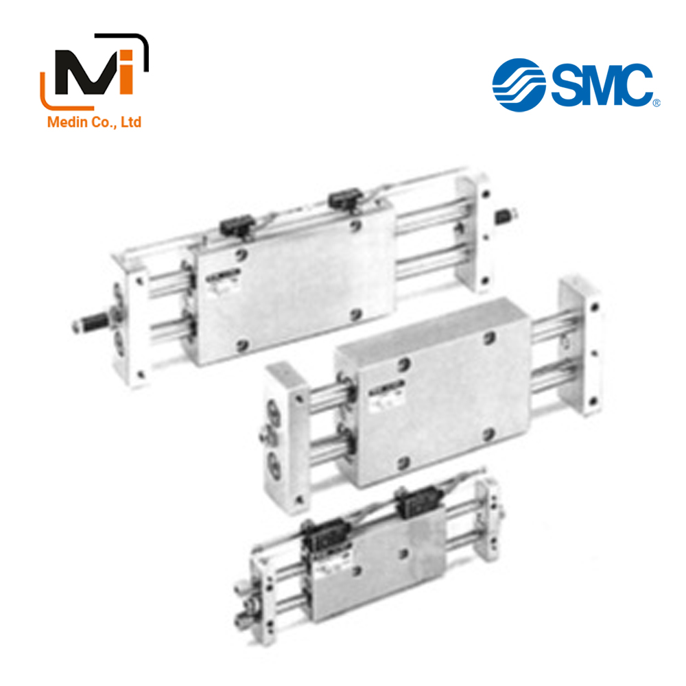
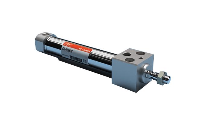
Xi Lanh Khí Nén SMC CX2 Series CDBX2N10 CDBX2N10-25 CDBX2H15
Ensures high positional accuracy. Slide Unit, Double-Rod Type, Slide Bearing CX2 Series.
Download
Xi Lanh Khí Nén SMC CX2 Series CDBX2N10 CDBX2N10-25 CDBX2H15 CDBX2H15-25 CDBX2H25 CDBX2H25-25 CDBX2H25-50 CDBX2H25-75
Slide Unit, Double-Rod Type, Slide Bearing CX2 Series Details
[Features] · Provided with shock absorbers to absorb impact and noise.· Auto switches can be installed.
· Smooth operation and high thrust.
· Mountable on the housing or on the plate.

Slide Unit, Double-Rod Type, Slide Bearing CX2 Series product image
Slide Unit, Double-Rod Type, Slide Bearing CX2 Series Specifications
Model Number Notation
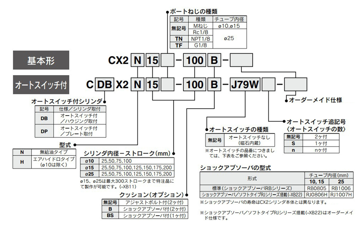
Model number example
Individual Made-to-Order Specifications
| Indicator symbol | Specifications/contents |
|---|---|
| -X138 | Adjustable stroke |
| -X146 | Hollow piston rod |
| -X168 | CX helical insert thread |
Made to order specifications
| Indicator symbol | Specifications/contents |
|---|---|
| -XB13 | Low speed cylinder (5 to 50 mm/s) |
| -XB22 | With shock absorber soft type RJ Series |
| -XC22 | Fluororubber seals |
Applicable Auto Switches
| Type | Special functions | Wire Exit | Indicator light | Wiring (output) | Load Voltage | Rail mounting | Applicable cylinder size | Lead wire length (m) | Pre-Wired Connector | Applicable load | ||||||||
|---|---|---|---|---|---|---|---|---|---|---|---|---|---|---|---|---|---|---|
| DC | AC | Vertical Outlet | Lateral Outlet | Housing mounting | Plate mounting | 0.5 (Nil) |
3 (L) |
5 (Z) |
None (N) |
|||||||||
| Solid state auto switch | – | Grommet | Yes | 3-wire (NPN) | 24 V | 5 V, 12 V | – | F7NV | F79 | ø15 (15‑mm diameter) / ø25 (25‑mm diameter) | ø10 (10‑mm diameter) / ø15 (15‑mm diameter) / ø25 (25‑mm diameter) | ● | ● | ○ | – | ○ | IC circuit | Relay, PLC |
| 3-wire (PNP) | F7PV | F7P | ● | ● | ○ | – | ○ | |||||||||||
| 2-Wire | 12 V | F7BV | J79 | ● | ● | ○ | – | ○ | – | |||||||||
| Connector | J79C | – | ● | ● | ● | ● | – | |||||||||||
| Diagnostic indication (2-color indicator) | Grommet | 3-wire (NPN) | 5 V, 12 V | F7NWV | F79W | ● | ● | ○ | – | ○ | IC circuit | |||||||
| 3-wire (PNP) | – | F7PW | ● | ● | ○ | – | ○ | |||||||||||
| 2-Wire | 12 V | F7BWV | J79W | ● | ● | ○ | – | ○ | – | |||||||||
| Improved water resistance product (2-color indicator) | **F7BAV | **F7BA | – | ● | ○ | – | ○ | |||||||||||
| With diagnostic output (2-color indicator) | 4-wire (NPN) | 5 V, 12 V | – | F79F | ● | ● | ○ | – | ○ | IC circuit | ||||||||
| Reed switch | – | Grommet | Yes | 3-wire | – | 5 V | – | – | A76H | ø15 (15‑mm diameter) / ø25 (25‑mm diameter) | ø10 (10‑mm diameter) / ø15 (15‑mm diameter) / ø25 (25‑mm diameter) | ● | ● | – | – | – | IC circuit | – |
| 2-Wire | – | – | 200 V | A72 | A72H | ● | ● | – | – | – | – | Relay, PLC | ||||||
| 24 V | 12 V | 100 V | A73 | A73H | ● | ● | ● | – | – | |||||||||
| NA | 5 V, 12 V | 100 V or less | A80 | A80H | ● | ● | – | – | – | IC circuit | ||||||||
| Connector | Yes | 12 V | – | A73C | – | ● | ● | ● | ● | – | – | |||||||
| NA | 5 V, 12 V | 24 V or less | A80C | – | ● | ● | ● | ● | – | IC circuit | ||||||||
| Grommet | Yes | 3-wire | – | 5 V | – | – | E76A | ø10 (diameter 10 mm) | – | ● | ● | – | – | – | ||||
| 2-Wire | 24 V | 12 V | 100 V | – | E73A | ● | ● | – | – | – | – | |||||||
| NA | 5 V, 12 V | 100 V or less | – | E80A | ● | ● | – | – | – | IC circuit | ||||||||
- *Water resistant type auto switches can be mounted to the above models, but the water resistance cannot be guaranteed. Check with the manufacturer regarding water-resistant types for the above model numbers.
- *Lead wire length symbols:
0.5 m: Nil (Example) F79W
3 m: L (Example) F79WL
5 m: Z (Example) F79WZ
None: N (Example) J79CN - *Solid state auto switches marked with ○ are produced to order.
- *Auto switches are shipped together (but not assembled).
Specifications
| Model | Non-lube | Air-hydro type | |
|---|---|---|---|
| Applicable fluids | Air | Hydraulic fluid | |
| Proof pressure | 1.5 MPa | ||
| Max. operating pressure | 1.0 MPa | ||
| Minimum operating pressure | CX2N10 | 0.15 MPa | – |
| CX2□15 | 0.15 MPa | ||
| CX2□25 | 0.10 MPa | ||
| Ambient temperature and working fluid temperature | -10°C to +60°C | ||
| Piston speed (non-lube) |
Adjusting bolt included | 30 to 200 mm/s | Refer to table (1). |
| With shock absorber | 30 to 500 mm/s | ||
| Cushioning | With shock absorber (option) | ||
| Stroke adjustable range | Standard stroke ±2 mm | ||
| Note 1)Max. load mass | CX2N10 | 9.8 N | |
| CX2□15 | 29.4 N | ||
| CX2□25 | 58.8 N | ||
| Non-rotating accuracy (Except piston rod deflection) |
CX2N10 | ±0.1° | |
| CX2□15 | ±0.04° | ||
| CX2□25 | ±0.02° | ||
| Accessories (options) | Straight knock pin (2 pcs.), Note 2)Adjusting bolt (-X138), Shock absorber | ||
- *Note 1) Place the center of gravity of the load as close to the center of the slide unit as possible during operation. Please consult with the manufacturer if they will be placed far apart.
- *Note 2) -X138 has a stroke adjustable range of 12.5 mm on one side.
Table (1) Air-Hydro/Piston Speed
| Model | Plate mounting | Housing mounting |
|---|---|---|
| CX2H15 | Note 1) Refer to the information below. | 5 to 50 mm/s |
| CX2H25 | 5 to 40 mm/s | 5 to 100 mm/s |
- *Note 1) Consult with the manufacturer if the air-hydro type is mounted on a plate.
- *Note 2) Consult with the manufacturer if units are used at a low speed (10 mm/s or faster) (when intermediate stops are not required) as -XB13 (low speed specification) is available.
- *Note 3) When using the air-hydro type, use the double side hydro unit.
Shock Absorber Specifications
| Shock absorber model | RB0805 | RB1006 | |
|---|---|---|---|
| Applicable slide unit model | CX2N10, CX2□15 | CX2□25 | |
| Maximum energy absorption J | 0.98 | 3.92 | |
| Stroke absorption mm | 5 | 6 | |
| Max. collision speed (m/sec) | 0.05 to 5 | ||
| Max. operating frequency cycle/min | 80 | 70 | |
| Max. allowable thrust N | 147 | 353 | |
| Ambient temperature range °C | -10 to 80 | ||
| Spring force N | Extended | 1.96 | 4.22 |
| Retracted | 3.83 | 6.18 | |
| Weight g | 15 | 25 | |
- *The above shows the maximum absorption energy per cycle. Accordingly, the operating frequency can be increased in accordance with the absorption energy.
- *The shock absorber service life may differ from that of the cylinder body depending on the operating conditions.
Theoretical Output List
(Unit: N)
| Model | Rod diameter (mm) |
Piston area (mm2) |
Operating pressure MPa | |||||||
|---|---|---|---|---|---|---|---|---|---|---|
| 0.2 | 0.3 | 0.4 | 0.5 | 0.6 | 0.7 | 0.8 | 0.9 | |||
| CX2N10 | 6 | 101 | 20 | 30 | 40 | 51 | 61 | 71 | 81 | 91 |
| CX2□15 | 8 | 207 | 41 | 62 | 83 | 104 | 124 | 145 | 166 | 186 |
| CX2□25 | 14 | 597 | 119 | 179 | 239 | 299 | 358 | 418 | 478 | 537 |
- *Note) Theoretical output (N) = Pressure (MPa) × Piston area (mm2)
Standard Strokes
| Model | Standard stroke (mm) | |||||||
|---|---|---|---|---|---|---|---|---|
| 25 | 50 | 75 | 100 | 125 | 150 | 175 | 200 | |
| CX2N10 | ● | ● | ● | ● | – | – | – | – |
| CX2□15 | ● | ● | ● | ● | ● | ● | ● | ● |
| CX2□25 | ● | ● | ● | ● | ● | ● | ● | ● |
Weight
(Increment: kg)
| Model | Standard stroke (mm) | |||||||
|---|---|---|---|---|---|---|---|---|
| 25 | 50 | 75 | 100 | 125 | 150 | 175 | 200 | |
| CX2N10 | 0.17 | 0.22 | 0.27 | 0.32 | – | – | – | – |
| CX2□15 | 0.23 | 0.34 | 0.45 | 0.56 | 0.67 | 0.78 | 0.89 | 1.00 |
| CX2□25 | 0.93 | 1.15 | 1.36 | 1.58 | 1.80 | 2.01 | 2.29 | 2.45 |
Structural Drawing / Parts List, Seal List
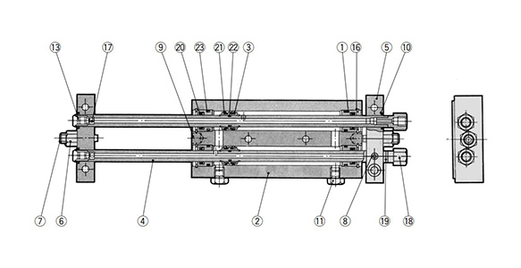
CX2N10 structural drawing
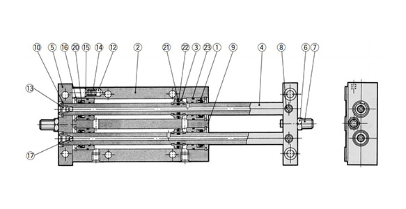
CX2N15/CX2N25 structural drawings
Parts List
| Number | Part name | Material | Note |
|---|---|---|---|
| 1 | Rod Cover | Aluminum bearing alloy | – |
| 2 | Housing | Aluminum Alloy | Hard Anodize |
| 3 | Piston | Aluminum Alloy | – |
| 4 | Piston rod | Carbon steel piping for machine constructions | Hard chrome plated |
| 5 | Plate | Aluminum Alloy | Anodized |
| 6 | Lock nut | Carbon steel | Nickel plating |
| 7 | Adjusting bolt | Chromium steel | Zinc chromate |
| 8 | Set screw (for fixing rods) | Chromium steel | Zinc chromate |
| 9 | Pin | Carbon steel | Quenched |
| 10 | Retaining Ring | Carbon tool steel | Phosphate coated |
| 11 | Plug | Carbon steel | Nickel plating |
| 12 | Magnet | – | – |
| 13 | Ball fixing screw | Chromium steel | Zinc chromate |
| 14 | Spring | Stainless steel | – |
| 15 | Type CR retaining ring | Carbon tool steel | – |
| 16 | Round R-shaped Retaining Rings | Carbon tool steel | Phosphate coated |
| 17 | Steel ball | High carbon chrome bearing steel | Heat treated |
| 18 | Socket | Brass | Electroless nickel plated |
| 19 | Gasket | NBR | – |
| 20 | Rod Gasket | – | |
| 21 | Piston Gasket | – | |
| 22 | Piston gasket | – | |
| 23 | Cylinder tube gasket | – |
Replacement Parts / Seal Kit
| Model | Order number | Content |
|---|---|---|
| CX2N10 | CX2N10-PS | A set of (20), (21), (23) listed above |
| CX2N15 | CX2N15-PS | |
| CX2N25 | CX2N25-PS |
- *Seal kit includes (20), (21), (23). Order the seal kit based on each bore size. (The piston gasket [22] is not replaceable.)
- *Since the seal kit does not include a grease pack, order it separately. Grease pack part number: GR-S-010 (10 g)
Slide Unit, Double-Rod Type, Slide Bearing CX2 Series Example Dimensions
ø10 (10‑mm Diameter) Basic Type: CX2N10-[Strokes: 25 to 100]□
(Unit: mm)
![ø10 (10‑mm diameter) Basic Type: CX2N10-[Strokes: 25 to 100]□ dimensional drawing](https://vn.misumi-ec.com/linked/vitem/mech/SMC1/221006301162/img/221006301162_jh_w05.jpg)
ø10 (10‑mm diameter) Basic Type: CX2N10-[Strokes: 25 to 100]□ dimensional drawing
| Model | F | G | L | P | Q | R | S | SS | Z | Adjusting bolt included | With shock absorber |
|---|---|---|---|---|---|---|---|---|---|---|---|
| ZZ | ZZ | ||||||||||
| CX2N10-25 | 9.5 | 19.5 | 38 | 48 | 103 | 28 | 27 | 67 | 94 | 132 | 176 |
| CX2N10-50 | 20 | 30 | 63 | 52 | 153 | 32 | 52 | 92 | 144 | 182 | 226 |
| CX2N10-75 | 25 | 35 | 88 | 67 | 203 | 47 | 77 | 117 | 194 | 232 | 276 |
| CX2N10-100 | 25 | 35 | 113 | 92 | 253 | 72 | 102 | 142 | 244 | 282 | 326 |
Housing Mounting Type with Auto Switch CDBX2N10-[Stroke]
(Unit: mm)
![Housing Mounting Type with Auto Switch CDBX2N10-[Stroke] dimensional drawing](https://vn.misumi-ec.com/linked/vitem/mech/SMC1/221006301162/img/221006301162_jh_w06.jpg)
Housing Mounting Type with Auto Switch CDBX2N10-[Stroke] dimensional drawing
Plate Mounting Type with Auto Switch CDPX2N10-[Stroke]
(Unit: mm)
![Plate Mounting Type with Auto Switch CDPX2N10-[Stroke] dimensional drawing](https://vn.misumi-ec.com/linked/vitem/mech/SMC1/221006301162/img/221006301162_jh_w07.jpg)
Plate Mounting Type with Auto Switch CDPX2N10-[Stroke] dimensional drawing
| Auto switch model | Hw | Ht | Hv |
|---|---|---|---|
| D-A7, D-A8 | 23 | 15 | 10.5 |
| D-F7□, D-J79, D-J79W, D-F7PW, D-F79F, D-F7BA, D-F7NT | 23 | 15 | 11.5 |
| D-A7□H, D-A80H | 22 | 15 | 11.5 |
| D-A73C, D-A80C | 23 | 17.5 | 17.5 |
| D-F7□V | 23 | 15 | 14 |
| D-J79C | 24 | 17.5 | 17 |
| D-F7LF | 30 | 15 | 11.5 |
- *For 25 strokes only, 2 magnets for auto switches are installed in the housing.
Basic Information
| Cylinder Operation Method | Double Acting | Rod Operation Method | Double rod | Main Body Shape | Guided |
|---|---|---|---|---|---|
| Type of Shaft Bearing | Slide bearing |
CDBX2N10-25-E73A
CDBX2N10-25-E73A-X138
CDBX2N10-25-E73AL
CDBX2N10-25-E73AL-X138
CDBX2N10-25-E73ALS
CDBX2N10-25-E73AS
CDBX2N10-25-E76A
CDBX2N10-25-E76ALS
CDBX2N10-25-E76AS
CDBX2N10-25-E80A
CDBX2N10-25-E80AL
CDBX2N10-25-E80ALS
CDBX2N10-25-E80AS
CDBX2N10-25-X138
CDBX2N10-25B
CDBX2N10-25B-E73A
CDBX2N10-25B-E73A-XC22
CDBX2H15-25-A73
CDBX2H15-25-F7BAL
CDBX2H15-25-F79W
CDBX2H15-25B
CDBX2H15-25BS
CDBX2H15-25BS-A73
CDBX2H15-25BS-J79
CDBX2H15-50
CDBX2H15-50-A73H
CDBX2H15-50-A73L
CDBX2H15-50-A73L3
CDBX2H15-50B
CDBX2H15-50B-A73
CDBX2H15-50B-J79W
CDBX2H15-50BS
CDBX2H25-25-F79
CDBX2H25-25B
CDBX2H25-25B-A73
CDBX2H25-25B-A73HS
CDBX2H25-25B-A73L
CDBX2H25-50
CDBX2H25-50-A73L
CDBX2H25-50B
CDBX2H25-50BS-A76HL
CDBX2H25-75
CDBX2H25-75-A73
CDBX2H25-75-A73L
CDBX2H25-75B
CDBX2H25-75BS-A73
———————-
👉 Xem thêm sản phẩm của SMC
Liên Hệ Medin Co., Ltd
- Công ty TNHH Mễ Đình được thành lập từ năm 2006.
- Là Đại lý uỷ quyền của SMC tại Việt Nam.
- Từ đó đến nay Medin luôn là Công ty dẫn đầu về lĩnh vực Tự Động Hoá ở thị trường trong và ngoài nước với hơn 1,000 khách hàng, cùng với rất nhiều dự án lớn nhỏ cho các nhà máy sản xuất.
- Chúng tôi cung cấp cho khách hàng những giải phát tuyệt vời nhất trong việc ứng dụng Tự Động Hoá vào sản xuất
- Phương châm: “Giải pháp của chúng tôi, lợi ích của khách hàng”
- Giá trị cốt lõi: “Uy tín là sự tồn tại của chúng tôi”

- Hơn 20 năm kinh nghiệm, chúng tôi có đội ngũ kỹ sư nhiều kinh nghiệm, có khả năng tư vấn, đưa ra giải pháp có lợi nhất cho khách hàng.
- Sự tin tưởng và đồng hành của khách hàng là động lực để Medin phát triển cao hơn và xa hơn.
👉 Nếu bạn có bất kỳ yêu cầu nào, vui lòng liên hệ với chúng tôi.
☎️ Hotline: 0902782082
![]() 3 Chi nhánh tại HCM, HN, Đà Nẵng
3 Chi nhánh tại HCM, HN, Đà Nẵng
👉 Tham khảo thêm bài viết trên Fanpage
👉 Tham khảo thêm video tại kênh Youtube
