Process Valve, 2 Port Valve For Flow Control VNB Series – Van điện từ khí nén SMC
Product Description
– Van điện từ khí nén SMC
A 2 port valve for flow control made by SMC.
[Features]
· Wide variety of applicable fluids
· Cylinder actuation by external pilot air
· Wide variations
Download
2 Port Valve For Flow Control, Process Valve, VNB Series Specifications – Van điện từ khí nén SMC

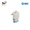
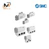
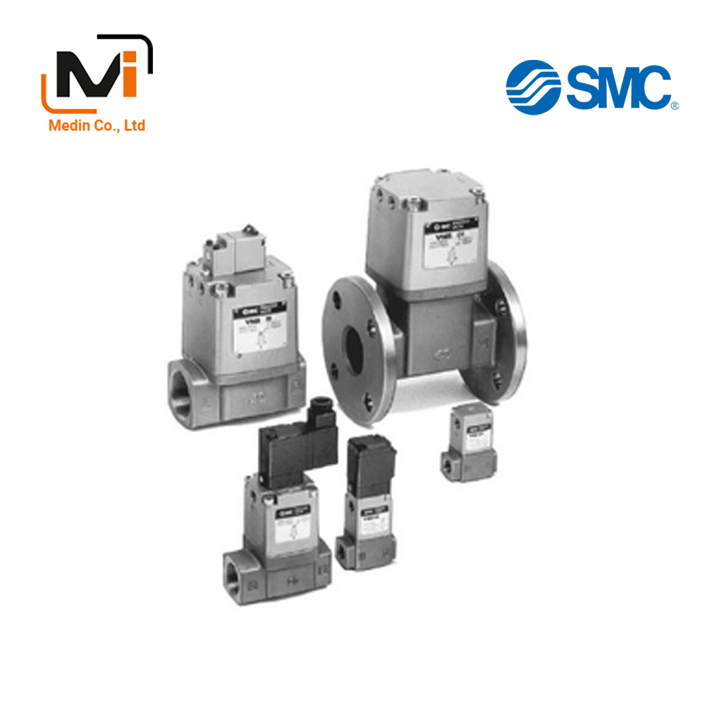
VNB Series external appearance
| Fluid (Main Piping) | Water, oil, air, vacuum, etc. | ||
|---|---|---|---|
| Fluid Temperature | VNB□□□A, VNB□1□B VNB□1□C | *1: -5 to +60°C | |
| VNB□0□B VNB□0□C |
*1: -5 to +99℃ (Water, oil, etc. Air-operated type only) |
||
| Ambient Temperature | *1 -5 to +50°C (60°C for air-operated type) | ||
| Proof Pressure | 1.5 MPa | ||
| Operating Pressure *4 | VNB□□1□ | Low vacuum to 0.5 MPa | |
| VNB□□2□ VNB□□3□ VNB□□4□ |
Low vacuum to 1 MPa | ||
| External Pilot Air | Pressure | VNB□□1□ VNB□□4□ |
0.25 to 0.7 MPa |
| VNB□□2□ VNB□□3□ |
0.1 + 0.25 × (operating pressure) to 0.25 + 0.25 × (operating pressure) MPa*3 | ||
| Lubrication | Not required (if lubricating, use turbine oil class 1 ISO VG32 *2) | ||
| Temperature | *1 -5 to +50°C (60°C for air-operated type) | ||
| Mounting Orientation | *5 Unrestricted | ||
*1: No freezing.
*2: Do not lubricate if seal material is EPR.
*3: For low vacuums, keep the pilot pressure in the 0.125 to 0.275‑MPa range.
*4: The pressure differential between port 1 (A) and 2 (B) must not exceed the maximum operating pressure.
*5: However, if the external pilot is a solenoid type, SMC recommends mounting the pilot solenoid valve in an upward facing vertical or horizontal orientation.
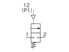
VNB□01/4 JIS symbol
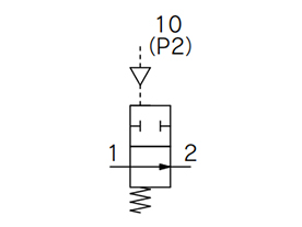
VNB□02 JIS symbol
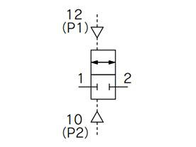
VNB□03 JIS symbol
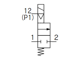
VNB□11/4 JIS symbol
*When using in vacuums, ensure flow direction is from port 1 (A) to port 2 (B).
Model
| Model | Piping Connection Port Diameter (Threaded) | Orifice Diameter ø[mm] |
Flow Rate Characteristics | Weight (kg) | |||||
|---|---|---|---|---|---|---|---|---|---|
| Measured with Air | Measured with Water | ||||||||
| C [dm3/(bar·sec)] | b | Cv | Kv | Conversion Cv | Air Operated Type | External Pilot Solenoid Type | |||
| VNB1□□□-6A | 1/8 | 7 | 3.3 | 0.29 | 0.80 | 0.9 | 1.0 | 0.3 | 0.4 |
| VNB1□□□-8A | 1/4 | 4.6 | 0.17 | 1.0 | 1.0 | 1.2 | |||
| VNB1□□□-10A | 3/8 | 4.7 | 0.18 | 1.1 | 1.1 | 1.3 | |||
| VNB2□4□-10A | 11 | 9.6 | 0.40 | 2.6 | 2.5 | 2.9 | 0.6 | 0.7 | |
| VNB2□□□-10A | 15 | 17 | 0.32 | 4.0 | 3.9 | 4.5 | |||
| VNB2□4□-15A | 1/2 | 11 | 9.6 | 0.40 | 2.6 | 2.7 | 3.1 | ||
| VNB2□□□-15A | 15 | 19 | 0.24 | 4.8 | 5.0 | 5.8 | |||
| VNB3□4□-20A | 3/4 | 14 | 18 | 0.42 | 5.4 | 5.0 | 5.8 | 0.9 | 1.0 |
| VNB3□□□-20A | 20 | 35 | 0.13 | 7.4 | 9.6 | 11 | |||
| Model | Piping Connection Port Diameter | Orifice Diameter ø[mm] |
Flow Rate Characteristics | Weight (kg) | ||||
|---|---|---|---|---|---|---|---|---|
| Thread | *Flange | Measured with Air | Measured with Water | |||||
| Effective Area (mm2) | Kv | Conversion Cv | Air Operated Type | External Pilot Solenoid Type | ||||
| VNB4□4□-25A | 1 | – | 16 | 130 | 6.1 | 7.0 | 1.4 | 1.5 |
| VNB4□□□-25A | 25 | 220 | 10.4 | 12 | ||||
| VNB5□4□-32A | 1 1/4 | – | 22 | 210 | 9.8 | 11 | 2.5 | 2.6 |
| VNB5□□□-32A | 32 | 320 | 15.6 | 18 | ||||
| VNB5□4□-32F | – | 32 | 22 | 210 | 9.8 | 11 | 5.7 | 5.8 |
| VNB5□□□-32F | 32 | 320 | 15.6 | 18 | ||||
| VNB6□4□-40A | 1 1/2 | – | 28 | 330 | 16.4 | 19 | 4.1 | 4.2 |
| VNB6□□□-40A | 40 | 500 | 24.2 | 28 | ||||
| VNB6□4□-40F | – | 40 | 28 | 330 | 16.4 | 19 | 7.7 | 7.8 |
| VNB6□□□-40F | 40 | 500 | 24.2 | 28 | ||||
| VNB7□4□-50A | 2 | – | 33 | 520 | 25.1 | 29 | 6.3 | 6.4 |
| VNB7□□□-50A | 50 | 770 | 37.2 | 43 | ||||
| VNB7□4□-50F | – | 50 | 33 | 520 | 25.1 | 29 | 11.4 | 11.5 |
| VNB7□□□-50F | 50 | 770 | 37.2 | 43 | ||||
*The accompanying flange should be JIS B 2210 10K (ordinary) or its equivalent.
Pilot Solenoid Valve Specifications
| Piping Connection Port Diameter | 6 A to 25 A | 32 A to 50 A | ||
|---|---|---|---|---|
| Pilot Solenoid Valve*1 | SF4-□□□-23 SF4-□D-23-Q SF4-□DZ-23-Q |
SF4-□□□1 SF4-□D1-Q SF4-□DZ1-Q |
||
| Electrical Entry | Grommet, grommet terminal Conduit terminal DIN Terminal |
Grommet, DIN terminal | ||
| Coil Rated Voltage (V) | AC (50/60 Hz) | 100 V, 200 V, other (semi-standard) | ||
| DC | 24 V, other (semi-standard) | |||
| Allowable Voltage Fluctuation | -15 to +10% of rated voltage | |||
| Temperature rise value | 35°C or less (when rated voltage is applied) | 50℃ or less (when rated voltage is applied) | ||
| Apparent Power | AC | Inrush | 5.6 VA (50 Hz), 5.0 VA (60 Hz) | 12.7 VA (50 Hz), 10.7 VA (60 Hz) |
| Holding | 3.4 VA (50 Hz), 2.3 VA (60 Hz) | 7.6 VA (50 Hz), 5.4 VA (60 Hz) | ||
| Power Consumption | DC | 1.8 W (without indicator light), 2 W (with indicator light) | 4 W (without indicator light), 4.2 W (with indicator light) | |
| Manual Operation | Non-locking push type Other (semi-standard) |
Non-locking push type | ||
*1 See catalog for information on ordering pilot solenoid valves.
*2 The vacuum pilot type pilot solenoid valve is VO307V-□□□1.
*3 The vacuum pilot-operated CE compliant pilot solenoid valve is VO307V-□D/DZ1-Q.
VNB102A-6A-B
VNB102A-8A
VNB102A-10A
VNB102A-N8A-B
VNB102AL-6A-B
VNB102AL-8A
VNB102AS-8A-B
VNB102AS-10A
VNB102AS-F10A
VNB102AS-N8A
VNB102AS-N8A-B
VNB102AS-N10A
VNB102B-6A
VNB102B-8A-B
VNB102B-10A-B
VNB102BS-N8A-B
VNB102BS-N10A
VNB102C-6A
VNB102C-10A
VNB102C-10A-B
VNB102CL-8A-B
VNB102CL-10A-B
VNB102CS-6A
VNB112A-6A-1G
VNB112A-6A-5D-B
VNB112A-6A-5EZA
VNB112A-6A-5EZA-B
VNB112A-6A-5G
VNB112A-6A-5G-B
VNB112A-8A-5D
VNB112A-8A-5DZ
VNB112A-10A-5DZB-Q
VNB112A-10A-5GS
VNB112A-10A-5GS-B
VNB112A-10A-6EZ-B
VNB112A-F6A-5DZ
VNB112A-F8A-5DZ
VNB112AL-8A-5GA
VNB112AS-6A-5G
VNB112AS-8A-1EZ
VNB112AS-8A-5EZB-B
VNB112AS-8A-5GS
VNB112AS-10A-1GS-B
VNB112AS-10A-2G
VNB112AS-10A-5DZ
VNB112B-6A-1EZ-B
VNB112B-6A-5DZ-Q
