MLGP Series Low Profile Guide Cylinder With Lock – Xi Lanh Khí Nén SMC
Product Description
– Xi Lanh Khí Nén SMC
MLGP Series Low Profile Guide Cylinder With Lock can hold the clamped state.
[Features]
· Prevents drops for press fitting jigs, etc.
· Drop protection for lifter.
· Locking position can be changed to accommodate external stopper positions and thickness of clamped workpieces.
· Simple and reliable locking system.
· Easy manual unlocking.
· 4 types of mounting are possible.
· 2 types of guide rod bearing parts suitable for different applications.
Download
MLGP Series Low Profile Guide Cylinder With Lock Details – Xi Lanh Khí Nén SMC

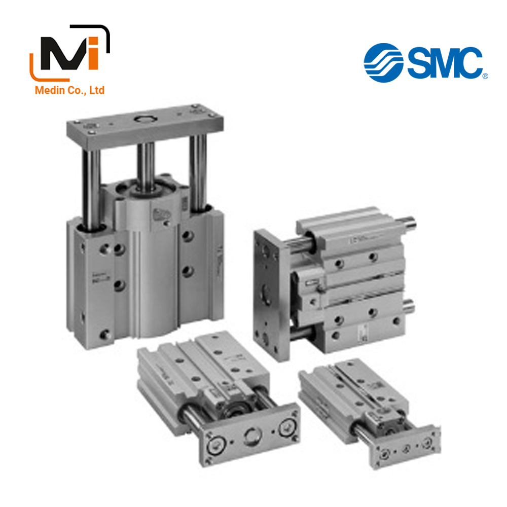
MLGP Series Low Profile Guide Cylinder With Lock product image
MLGP Series Low Profile Guide Cylinder With Lock Specifications
Model Number Notation
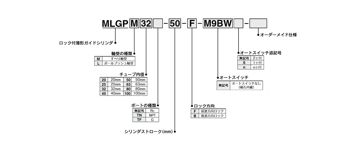
Model number examples
Made to Order Specifications
| Symbols | Specifications/contents |
|---|---|
| -XC87 | Heavy duty specification ø40 to 100 (diameter 40 to 100 mm) only |
Cylinder Specification
| Tube Inner Diameter (mm) | 20 | 25 | 32 | 40 | 50 | 63 | 80 | 100 |
|---|---|---|---|---|---|---|---|---|
| Action | Double-acting type | |||||||
| Fluid | Air | |||||||
| Proof Pressure | 1.5 MPa | |||||||
| Maximum operating pressure | 1.0 MPa | |||||||
| Minimum operating pressure | 0.2 MPa* | |||||||
| Ambient and Working Fluid Temperature | -10°C to 60°C (no freezing) | |||||||
| Piston Speed | 50 to 400 mm/s | |||||||
| Cushioning | Rubber bumper at both ends | |||||||
| Lubrication | Not required (non-lubricated) | |||||||
| Stroke Length Tolerance | (0 to +1.5) mm | |||||||
| Port size (Rc, NPT, G) | 1/8 | 1/4 | 3/8 | |||||
*When the unlocking air and cylinder operating air are not common, the minimum operating pressure is 0.15 MPa.
(The minimum operating pressure for the cylinder alone is 0.15 MPa.)
Lock Specifications
| Tube Inner Diameter (mm) | 20 | 25 | 32 | 40 | 50 | 63 | 80 | 100 |
|---|---|---|---|---|---|---|---|---|
| Locking Method | Spring locking (exhaust locking) | |||||||
| Unlocking pressure | 0.2 MPa or more | |||||||
| Locking Starting Pressure | 0.05 MPa or less | |||||||
| Locking Direction | One direction (extension locking, retraction locking) | |||||||
| Maximum operating pressure | 1.0 MPa | |||||||
| Unlocking port size (Rc, NPT, G) | M5 × 0.8 | 1/8 | 1/4 | |||||
| Holding force (maximum static load) (N)* | 157 | 245 | 402 | 629 | 982 | 1,559 | 2,513 | 3,927 |
*The holding force (maximum static load) indicates the maximum capacity, not the normal holding capacity.
Diagram Examples
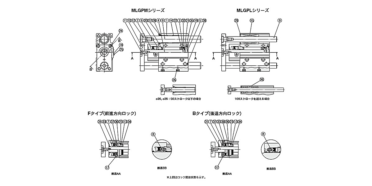
Diagram: ø20 (20-mm diameter), ø25 (25-mm diameter), ø32 (32-mm diameter)
Components
| Number | Part Name | Material | Notes | |
|---|---|---|---|---|
| 1 | Body | Aluminum alloy | Hard anodized aluminum | |
| 2 | Lock body | Aluminum alloy | Hard anodized aluminum | |
| 3 | Piston | Aluminum alloy | Chromate | |
| 4 | Piston rod | ø20 (20‑mm diameter), ø25 (25‑mm diameter) | Stainless steel | Hard chrome plated |
| ø32 mm | Carbon steel | |||
| 5 | Head cover | Aluminum alloy | Chromate | |
| 6 | Intermediate collar | Aluminum alloy | Chromate | |
| 7 | Lock ring | Carbon steel | Heat treated | |
| 8 | Brake spring | Steel wire | Zinc chromate | |
| 9 | Guide rod | Type M | Carbon steel | Hard chrome plated |
| Type L | High carbon chrome bearing steel | Hard chrome plated | ||
| 10 | Plate | Rolled steel | Nickel plated | |
| 11 | Plate mounting bolt | Chrome molybdenum steel | Nickel plated | |
| 12 | Bolt for guide | Chrome molybdenum steel | Nickel plated | |
| 13 | Bushing | Resin/Copper alloy (Multiple layers) | – | |
| 14 | Bushing | Resin/Copper alloy (Multiple layers) | MLGPM type | |
| 15 | Ball bushing | – | MLGPL type | |
| 16 | Spacer | Aluminum alloy | Chromated (MLGPL type only) | |
| 17 | Pivot | Chrome molybdenum steel | Heat treated, hard chrome plated | |
| 18 | Dust cover | Stainless steel | – | |
| 19 | Type C Retaining Ring for Hole | Carbon tool steel | Phosphate conversion coating | |
| 20 | Damper A | Urethane | – | |
| 21 | Damper B | Urethane | – | |
| 22 | Magnet | – | – | |
| 23 | Parallel pin | Stainless steel | – | |
| 24 | Hex Socket Head Cap Screw | Chrome molybdenum steel | – | |
| 25 | Dust cover holding bolt | Carbon steel | – | |
| 26 | Hexagon socket head plug | Carbon steel | – | |
| 27 | Holder | Resin | MLGPM type only | |
| 28 | Felt | Felt | MLGPM type only | |
| 29 | Type C Retaining Ring for Hole | Carbon tool steel | Phosphate coated (MLGPL type only) | |
| 30 | Rod packing | NBR | – | |
| 31 | Scraper | NBR | – | |
| 32 | Piston packing | NBR | – | |
| 33 | Lock ring seal | NBR | – | |
| 34 | Gasket A | NBR | – | |
| 35 | Gasket B | NBR | – | |
| 36 | Lock body gasket | NBR | – | |
| 37 | Lock release bolt | Chrome molybdenum steel | – | |
| 38 | Steel ball | High carbon chrome bearing steel | – | |
MLGP Series Low Profile Guide Cylinder With Lock Example Dimensions
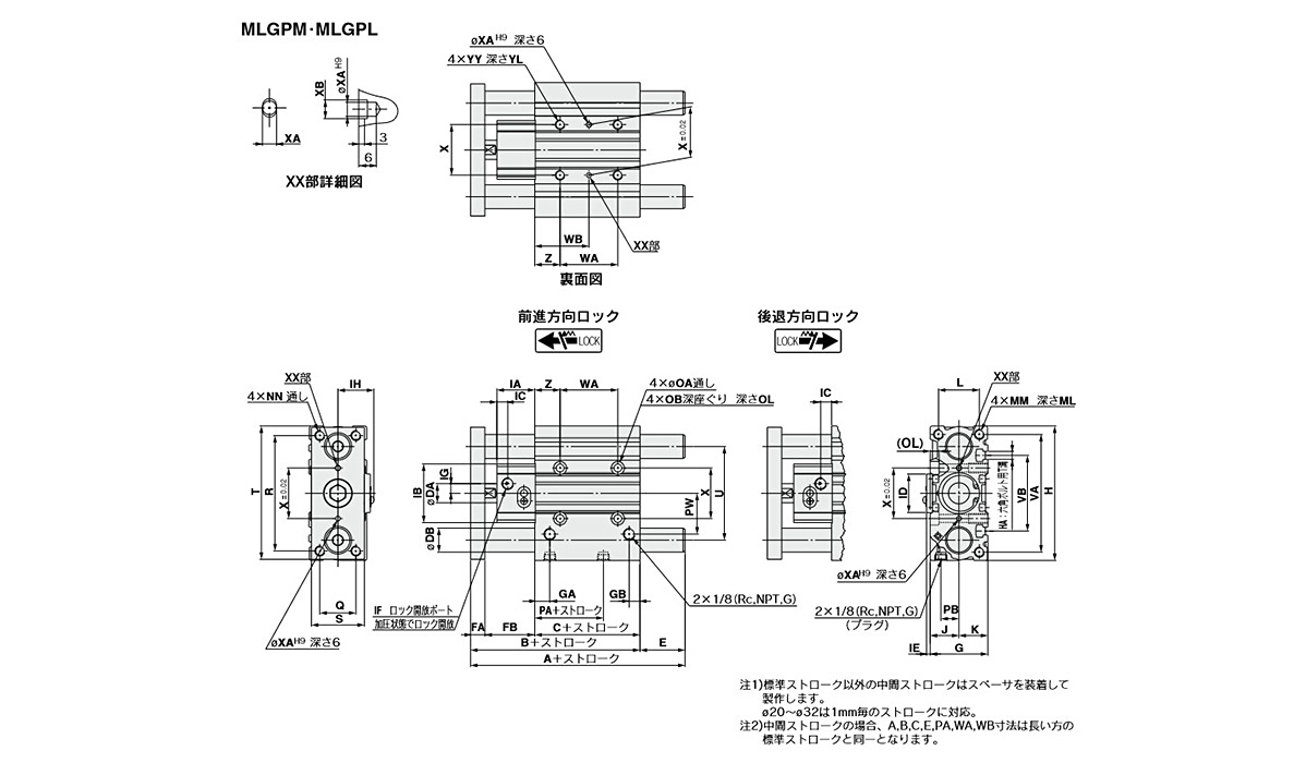
Dimensional drawings: MLGPM, MLGPL
MLGPM, MLGPL Common Dimensions
(Units: mm)
| Tube inner diameter (mm) |
Standard Stroke (mm) |
B | C | DA | FA | FB | G | GA | GB | H | HA | IA | IB | IC | ID | IE | IF | ||||
|---|---|---|---|---|---|---|---|---|---|---|---|---|---|---|---|---|---|---|---|---|---|
| Extension locking | Retraction locking | Rc, NPT | G | ||||||||||||||||||
| Rc, NPT | G | Rc, NPT | G | ||||||||||||||||||
| 20 | 20, 30, 40, 50, 75, 100, 125 150, 175, 200, 250, 300, 350 |
79.5 | 37 | 10 | 10 | 32.5 | 36 | 10.5 | 8.5 | 83 | M5 | 26.5 | 36 | 9.5 | 9.5 | 6 | 6 | – | – | M5 × 0.8 | M5 × 0.8 |
| 25 | 84 | 37.5 | 12 | 10 | 36.5 | 42 | 11.5 | 9 | 93 | M5 | 30.5 | 40 | 10 | 10 | 7.5 | 7.5 | – | – | M5 × 0.8 | M5 × 0.8 | |
| 32 | 25, 50, 75, 100, 125, 150, 175, 200, 250, 300, 350 | 91 | 37.5 | 16 | 12 | 41.5 | 48 | 12.5 | 9 | 112 | M6 | 31.5 | 49 | 9 | 8 | 9 | 4 | 32 | 3 | 1/8 | M5 × 0.8 |
(Units: mm)
| Tube inner diameter (mm) |
IG | IH | J | K | L | MM | ML | NN | OA | OB | OL | PA | PB | PW | Q | R | S | T | U | VA | VB |
|---|---|---|---|---|---|---|---|---|---|---|---|---|---|---|---|---|---|---|---|---|---|
| 20 | 6.5 | 21.2 | 18 | 18 | 24 | M5 × 0.8 | 13 | M5 × 0.8 | 5.4 | 9.5 | 5.5 | 12.5 | 10.5 | 25 | 18 | 70 | 30 | 81 | 54 | 72 | 44 |
| 25 | 7 | 23.2 | 21 | 21 | 30 | M6 × 1.0 | 15 | M6 × 1.0 | 5.4 | 9.5 | 5.5 | 12.5 | 13.5 | 30 | 26 | 78 | 38 | 91 | 64 | 82 | 50 |
| 32 | 8 | 30.2 | 24 | 24 | 34 | M8 × 1.25 | 20 | M8 × 1.25 | 6.6 | 11 | 7.5 | 7 | 15 | 35.5 | 30 | 96 | 44 | 110 | 78 | 98 | 63 |
(Units: mm)
| Tube inner diameter (mm) |
WA | ||||||
|---|---|---|---|---|---|---|---|
| st ≤ 25 | st ≤ 30 | 25 < st ≤ 100 | 30 < st ≤ 100 | 100 < st ≤ 200 | 200 < st ≤ 300 | 300 < st ≤ 350 | |
| 20 | – | 24 | – | 44 | 120 | 200 | 300 |
| 25 | – | 24 | – | 44 | 120 | 200 | 300 |
| 32 | 24 | – | 48 | – | 124 | 200 | 300 |
(Units: mm)
| Tube inner diameter (mm) |
WB | X | XA | XB | YY | YL | Z | ||||||
|---|---|---|---|---|---|---|---|---|---|---|---|---|---|
| st ≤ 25 | st ≤ 30 | 25 < st ≤ 100 | 30 < st ≤ 100 | 100 < st ≤ 200 | 200 < st ≤ 300 | 300 < st ≤ 350 | |||||||
| 20 | – | 29 | – | 39 | 77 | 117 | 167 | 28 | 3 | 3.5 | M6 × 1.0 | 12 | 17 |
| 25 | – | 29 | – | 39 | 77 | 117 | 167 | 34 | 4 | 4.5 | M6 × 1.0 | 12 | 17 |
| 32 | 33 | – | 45 | – | 83 | 121 | 171 | 42 | 4 | 4.5 | M8 × 1.25 | 16 | 21 |
Dimensions: MLGPM (Slide Bearing) / A, DB, E
(Units: mm)
| Tube inner diameter (mm) |
A | DB | E | ||||
|---|---|---|---|---|---|---|---|
| st ≤ 50 | 50 < st ≤ 200 | 200 < st | st ≤ 50 | 50 < st ≤ 200 | 200 < st | ||
| 20 | 79.5 | 111 | 148.5 | 12 | 0 | 31.5 | 69 |
| 25 | 84 | 115.5 | 152.5 | 16 | 0 | 31.5 | 68.5 |
| 32 | 128.5 | 133.5 | 171.5 | 20 | 37.5 | 42.5 | 80.5 |
Dimensions: MLGPL (Ball Bushing Bearing) / A, DB, E
| Tube inner diameter (mm) |
A | DB | E | ||||||||||
|---|---|---|---|---|---|---|---|---|---|---|---|---|---|
| st ≤ 30 | st ≤ 50 | 30 < st ≤ 100 | 50 < st ≤ 100 | 100 < st ≤ 200 | 200 < st ≤ 350 | st ≤ 30 | st ≤ 50 | 30 < st ≤ 100 | 50 < st ≤ 100 | 100 < st ≤ 200 | 200 < st ≤ 350 | ||
| 20 | 89.5 | – | 106.5 | – | 130.5 | 148.5 | 10 | 10 | – | 27 | – | 51 | 69 |
| 25 | 100 | – | 116 | – | 135 | 152.5 | 13 | 16 | – | 32 | – | 51 | 68.5 |
| 32 | – | 112.5 | – | 129.5 | 149.5 | 171.5 | 16 | – | 21.5 | – | 38.5 | 58.5 | 80.5 |
Basic Information
| Cylinder Operation Method | Double Acting | Rod Operation Method | Single Rods | Main Body Shape | Guided |
|---|---|---|---|---|---|
| Environment, Applications | Standard | Cushion | Rubber bumper at both ends | Operating Pressure(MPa) | 0.2 to 1.0 |
| Specifications | Built-in magnet |
MLGPL20-10-F-M9N
MLGPL20-15-F-M9BWL
MLGPL20-15-F-Y69BL
MLGPL20-20-B
MLGPL20-20-B-A93L
MLGPL20-20-B-M9B
MLGPL20-20-B-M9BAL
MLGPL20-20-B-M9BAVL3
MLGPL25-10-B
MLGPL25-10-F
MLGPL25-15-B-M9BA
MLGPL25-15-B-Y7BW
MLGPL25-20-B
MLGPL25-20-B-M9BL
MLGPL25-20-B-M9BW
MLGPL25-20-B-M9BWL
MLGPL25-20-B-M9BWVL
MLGPL25-20-B-M9BWVSDPC
MLGPL32-10-F
MLGPL32-10-F-Y69AL
MLGPL32-12-F-M9BWZ
MLGPL32-15-B-M9BL
MLGPL32-17-F-M9BWZ
MLGPL32-20-B
MLGPL32-20-B-Y7BW
MLGPL32-20-F
MLGPL32-25-B
MLGPL32-25-B-M9B
MLGPL40-15-B-M9BL
MLGPL40-15-B-M9BWL
MLGPL40-20-B
MLGPL40-20-B-M9BWL
MLGPL40-20-F
MLGPL40-20-F-Y7BW
MLGPL40-25-B
MLGPL40-25-B-M9B
MLGPL50-20-B-M9BWL
MLGPL50-20-F
MLGPL50-25-B
MLGPL50-25-B-A93L
MLGPL50-25-B-M9BW
MLGPL50-25-B-M9BWSDPC
MLGPL50-25-B-P4DWSCS
MLGPL50-25-B-P5DWL
MLGPL50-25-B-Y7BASBPC
MLGPL50-25-B-Y7BASDPC
MLGPL50-25-B-Y7BW
MLGPL50-25-B-Y7BWSDPC
MLGPL63-20-F
MLGPL63-25-B
MLGPL63-25-B-A93L
MLGPL63-25-B-M9B
MLGPL63-25-B-M9BWSDPC
MLGPL63-25-B-M9NMDPC
MLGPL63-25-B-Y7BAL
MLGPL63-25-B-Y7BW
MLGPL63-25-B-Y59BZ
MLGPL80-20-B-A93
MLGPL80-20-B-A933
MLGPL80-20-F
MLGPL80-25-B
MLGPL80-25-B-M9BASDPC
MLGPL80-25-B-M9BL
MLGPL80-25-B-M9BM
MLGPL80-25-B-M9BW
MLGPL80-25-B-M9BWL
MLGPL80-25-B-M9BWSDPC
MLGPL80-25-B-Y59B
MLGPL80-25-F
MLGPL80-25-F-M9BWL
MLGPL80-25-F-M9NV
MLGPL100-20-F
MLGPL100-25-F
MLGPL100-30-F
MLGPL100-40-F
MLGPL100-50-B
MLGPL100-50-B-M9BVL
MLGPL100-50-B-M9BW
MLGPL100-50-B-M9BWL
MLGPL100-50-B-M9BWS
MLGPL100-50-B-M9BWVL
MLGPL100-50-B-P4DWSC
MLGPL100-50-B-P5DWSC
MLGPL100-50-B-Y69BL

