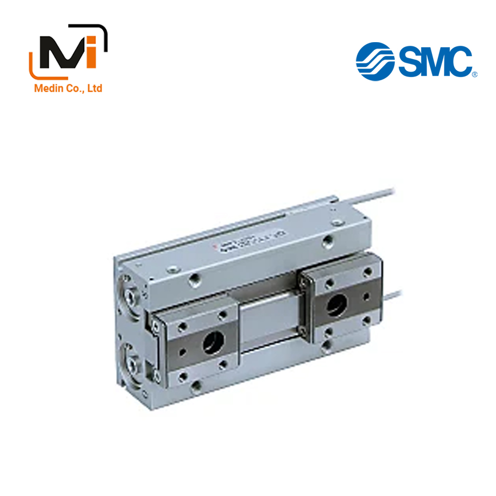
Xi Lanh Kẹp SMC Gripper MHF2 Series Low Profile Air Gripper
Low Profile Air Gripper MHF2 Series – Xi Lanh Kẹp SMC
Download
MHF2 Series Low Profile Air Gripper Specifications – Xi Lanh Kẹp SMC
[Features] · Low profile: Height is approximately 1/3 smaller (compared to product with equivalent gripping force from the MHZ2 Series).· Contributes to device space saving measures.
· Reduces bending moments.
· Operates smoothly, providing improved accuracy.
· The stroke length can be selected.
& nbsp3 standard stroke lengths (short, middle and length) are available for each bore size.
& nbspYou can select the optimal stroke for each workpiece.
· Improved mounting repeatability.
· Piping from either direction.
· Easy positioning for mounting attachments.
· Wiring and piping can be centralized.
· High degree of mounting flexibility.
& nbspBracket not required.
& nbspCan help keep mounting height to a minimum.
· A compact design in which a large amount of gripping force is provided through the use of a double piston mechanism.
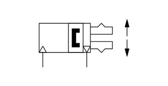
Double acting, inner-diameter grip JIS symbol
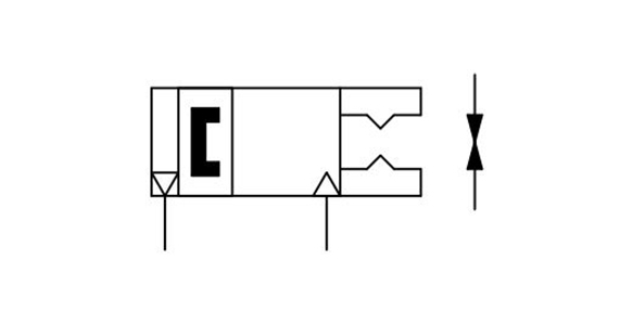
Double acting, outer-diameter grip JIS symbol
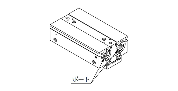
Body option: axial ported (Nil) external appearance
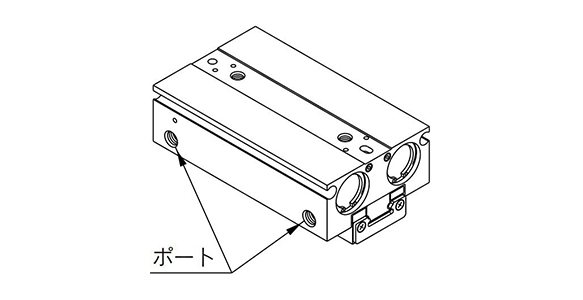
Body option: side ported (R) external appearance
| Fluid | Air | |
|---|---|---|
| Operating pressure | ø8 (diameter 8 mm): 0.15 to 0.7 MPa | |
| ø12 to 20 (diameter 12 to 20 mm): 0.1 to 0.7 MPa | ||
| Ambient and fluid temperature | -10°C to +60℃ (no freezing) | |
| Repeatability | ±0.05 mm*1 | |
| Maximum operating frequency | Short stroke | 120 c.p.m. |
| Middle stroke | 120 c.p.m. | |
| Long stroke | 60 c.p.m. | |
| Lubrication | Non-lube | |
| Action | Double acting | |
| Auto switch (option)*2 | Solid state auto switch (3-wire, 2-wire) | |
*1 Value when no unbalanced load is applied to the finger. If the finger is subjected to an unbalanced load, the backlash of the rack pinion can be up to ±0.15 mm.
*2 See the manufacturer’s catalog for detailed specifications of auto switches.
Model
| Action | Model | Bore size (mm) |
Gripping force*1 | Opening/closing stroke (Both sides) mm |
Weight*2 g |
Internal capacity (cm3) | |
|---|---|---|---|---|---|---|---|
| Gripping force per finger effective value N | Finger opening side | Finger closing side | |||||
| Double acting | MHF2-8D | 8 | 19 | 8 | 65 | 0.7 | 0.6 |
| MHF2-8D1 | 16 | 85 | 1.1 | 1.0 | |||
| MHF2-8D2 | 32 | 120 | 2.0 | 1.9 | |||
| MHF2-12D | 12 | 48 | 12 | 155 | 1.9 | 1.6 | |
| MHF2-12D1 | 24 | 190 | 3.3 | 3.0 | |||
| MHF2-12D2 | 48 | 275 | 6.1 | 5.8 | |||
| MHF2-16D | 16 | 90 | 16 | 350 | 4.9 | 4.1 | |
| MHF2-16D1 | 32 | 445 | 8.2 | 7.4 | |||
| MHF2-16D2 | 64 | 650 | 14.9 | 14.0 | |||
| MHF2-20D | 20 | 141 | 20 | 645 | 8.7 | 7.3 | |
| MHF2-20D1 | 40 | 850 | 15.1 | 13.7 | |||
| MHF2-20D2 | 80 | 1,225 | 28.0 | 26.6 | |||
*1 Values based on pressure of 0.5 MPa, gripping point L = 20 mm.
*2 Values above do not include auto switch weight.
Structure drawing
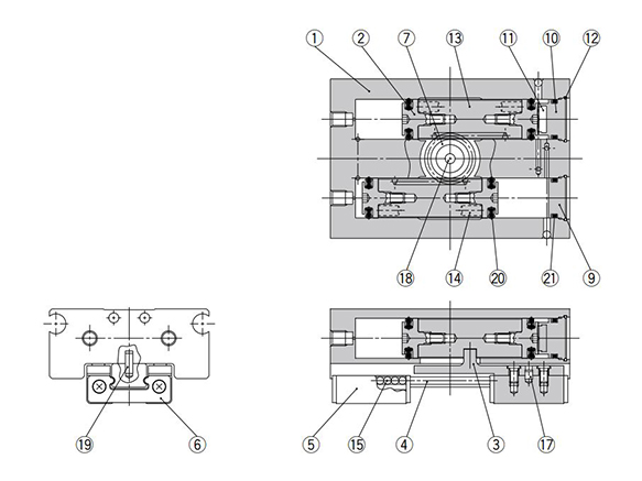
MHF2-8D, MHF2-8D1 structure drawing
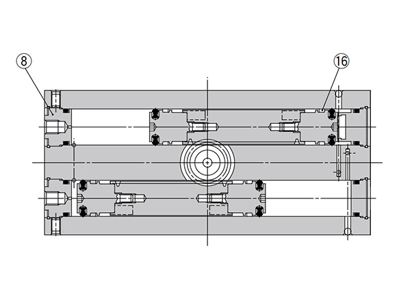
MHF2-8D2 structure drawing
| No. | Description | Material | Note |
|---|---|---|---|
| 1 | Body | Aluminum alloy | Hard anodizing |
| 2 | Piston | Stainless steel | – |
| 3 | Joint | Stainless steel | Heat treated |
| 4 | Guide rail | Stainless steel | Heat treated |
| 5 | Finger | Stainless steel | Heat treated |
| 6 | Roller stopper | Stainless steel | – |
| 7 | Pinion | Carbon steel | Nitrided |
| 8 | Cap A | Aluminum alloy | Clear anodized |
| 9 | Cap B | Aluminum alloy | Clear anodized |
| 10 | Cap C | Aluminum alloy | Clear anodized |
| No. | Description | Material | Note |
|---|---|---|---|
| 11 | Head bumper | Urethane rubber | – |
| 12 | Clip | Stainless steel wire | – |
| 13 | Rack | Stainless steel | Nitrided |
| 14 | Magnet | – | Nickel plating |
| 15 | Steel ball | High carbon chrome bearing steel | – |
| 16 | Wear ring | Synthetic resin | – |
| 17 | Cylindrical roller | High carbon chrome bearing steel | – |
| 18 | Needle roller | High carbon chrome bearing steel | – |
| 19 | Parallel pin | Stainless steel | – |
| 20 | Piston seal | NBR | – |
| 21 | Gasket | NBR | – |
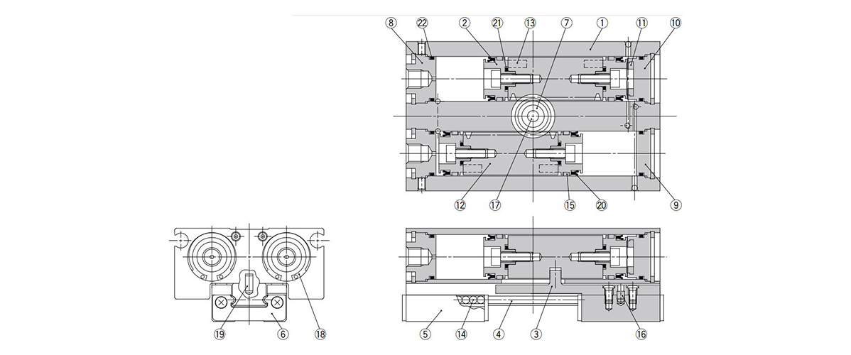
MHF2-12D□ to 20D□ structure drawing
| No. | Description | Material | Note |
|---|---|---|---|
| 1 | Body | Aluminum alloy | Hard anodizing |
| 2 | Piston | Aluminum alloy | Clear anodized |
| 3 | Joint | Stainless steel | Heat treated |
| 4 | Guide rail | Stainless steel | Heat treated |
| 5 | Finger | Stainless steel | Heat treated |
| 6 | Roller stopper | Stainless steel | – |
| 7 | Pinion | Carbon steel | Nitrided |
| 8 | Cap A | Aluminum alloy | Clear anodized |
| 9 | Cap B | Aluminum alloy | Clear anodized |
| 10 | Cap C | Aluminum alloy | Clear anodized |
| 11 | Head bumper | Urethane rubber | – |
| 12 | Rack | Stainless steel | Nitrided |
| 13 | Magnet | – | Nickel plating |
| 14 | Steel ball | High carbon chrome bearing steel | – |
| 15 | Wear ring | Synthetic resin | – |
| 16 | ø12 (diameter 12 mm): cylindrical roller | High carbon chrome bearing steel | – |
| ø16 to 20 (diameter 16 to 20 mm): parallel pin | Stainless steel | – | |
| 17 | Needle roller | High carbon chrome bearing steel | – |
| 18 | ø12 (diameter 12 mm): round R-shaped retaining ring | Carbon steel | Phosphate coated |
| ø16 to 20 (diameter 16 to 20 mm): C-shaped retaining ring | |||
| 19 | Parallel pin | Stainless steel | – |
| 20 | Piston seal | NBR | – |
| 21 | Gasket | NBR | – |
| 22 | Gasket | NBR | – |
External dimensional drawing
(Unit: mm)
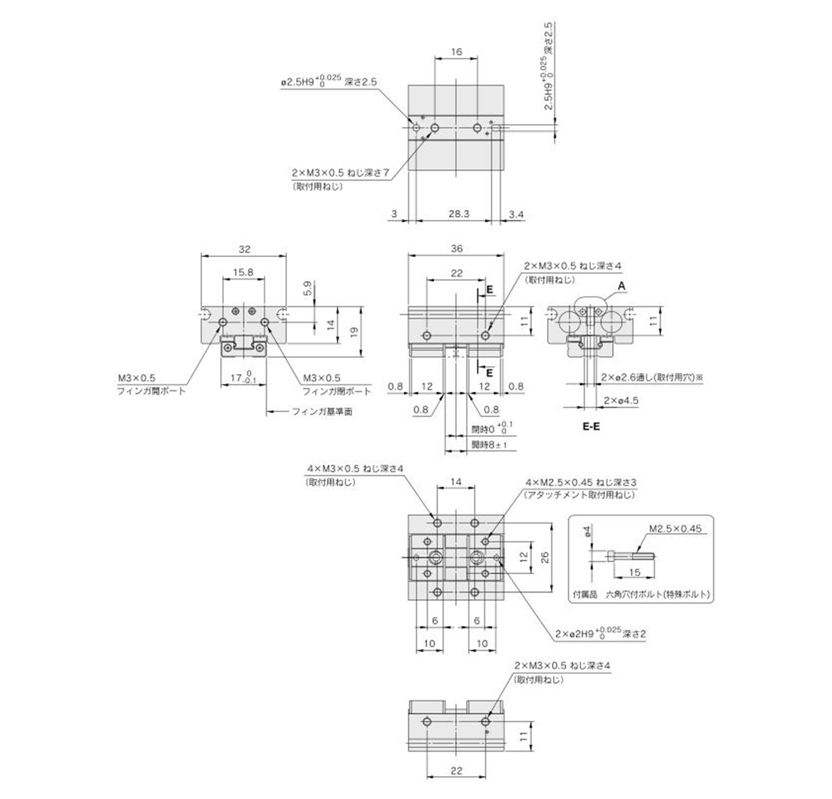
MHF2-8D dimensional drawing
*If mounting holes are used, use the hex socket head cap screw (accessory).
(Unit: mm)
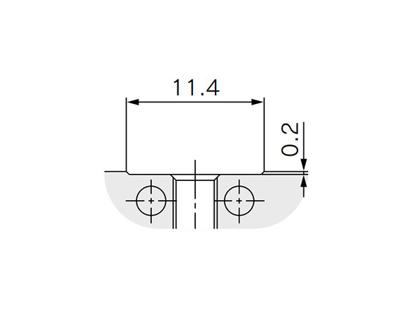
MHF2-8D A detail dimensional drawing
(Unit: mm)
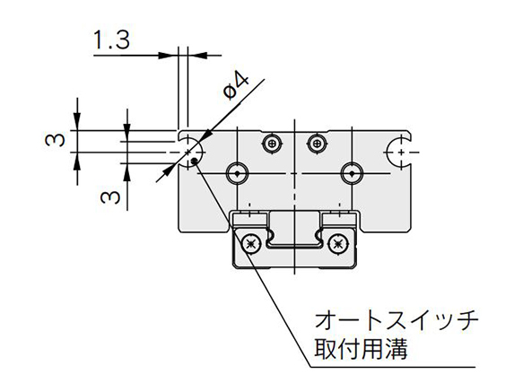
MHF2-8D auto switch mounting groove dimensional drawing
Precautions
- *Be sure to read the product precautions in the manufacturer’s catalog before use.
- *See the manufacturer’s catalog for information other than the above.
Basic Information
| Type | Main body | Gripping Methods | Pinch, Chuck Type / Open, Chuck Type | Number of Fingers | 2 pcs. |
|---|---|---|---|---|---|
| Main Body Shape | Square Shape (Flat Shape) | Operation Method | Double Acting Type |
MHF2-12D1
MHF2-12D1-M9BL
MHF2-12D1-M9BVL
MHF2-12D1-M9BW
MHF2-12D1-M9N
MHF2-12D1-M9NL
MHF2-12D1-M9NW
MHF2-16D
MHF2-16D1
MHF2-16D1-M9B
MHF2-16D1-M9BL
MHF2-16D1-M9BLS
MHF2-16D1-M9BMS
MHF2-16D1-M9BV
MHF2-20D
MHF2-20D1
MHF2-20D1-M9B
MHF2-20D1-M9BL
MHF2-20D1-M9BV
MHF2-20D1-M9N
MHF2-20D1-M9NL
MHF2-20D1-M9NL3
MHF2-8D1
MHF2-8D1-M9BL
MHF2-8D1-M9BLS
MHF2-8D1-M9BV
MHF2-8D1-M9BW
MHF2-8D1-M9BWL
MHF2-8D1-M9NL
MHF2-12D
MHF2-12D1
MHF2-12D1-M9B
MHF2-12D1-M9B3
MHF2-12D1-M9B3-X63
MHF2-12D1-M9B-X4
MHF2-12D1-M9B-X63
MHF2-12D1-M9B-X79A
MHF2-12D1-M9B-X83A1
MHF2-12D1-M9B-X83A2
MHF2-16D
MHF2-16D1
MHF2-16D1-M9B
MHF2-16D1-M9B3
MHF2-16D1-M9B4
MHF2-16D1-M9B-X4
MHF2-16D1-M9B-X83A1
MHF2-16D1-M9B-X83A2
MHF2-20D1
MHF2-20D1-M9B
MHF2-20D1-M9B3
MHF2-20D1-M9B-X4
MHF2-20D1-M9B-X5
MHF2-20D1-M9B-X63
MHF2-20D1-M9B-X79
MHF2-20D1-M9B-X83A1
MHF2-20D1-M9B-X83C1
MHF2-20D1-M9B-X83C2
MHF2-20D1-M9BA
MHF2-20D1-M9BAL
MHF2-20D1-M9BAL3
MHF2-20D1-M9BAL-X4
MHF2-8D
MHF2-8D1
MHF2-8D1-M9B
MHF2-8D1-M9B3
MHF2-8D1-M9B4
MHF2-8D1-M9B-X63
MHF2-8D1-M9B-X83A1
MHF2-8D1-M9B-X83A2
MHF2-8D1-M9B-X83B2
MHF2-8D1-M9B-X83C1
MHF2-8D1-M9B-X83C2
MHF2-8D1-M9BA
MHF2-8D1-M9BAL
MHF2-8D1-M9BAL-X5
Giới thiệu SMC Việt Nam
SMC là thương hiệu hàng đầu thế giới trong lĩnh vực công nghệ khí nén, cung cấp các giải pháp tiên tiến nhằm hỗ trợ tự động hóa và tối ưu hóa quy trình sản xuất.
Với nền tảng vững chắc trong ngành, SMC Việt Nam luôn đi đầu trong việc nghiên cứu, đổi mới và phát triển sản phẩm, góp phần nâng cao năng suất và tiết kiệm lao động cho các doanh nghiệp công nghiệp.
Với phương châm “đóng góp vào tự động hóa và tiết kiệm lao động trong ngành công nghiệp”, SMC Việt Nam không ngừng cải tiến và mang đến những sản phẩm công nghệ tiên tiến nhất.
SMC Việt Nam cam kết cung cấp những giải pháp hiện đại, giúp khách hàng duy trì lợi thế cạnh tranh trên thị trường.
Medin Company cung cấp các sản phẩm SMC tại Việt Nam.
Đa dạng các sản phẩm và giải pháp khí nén phục vụ cho nhiều ngành công nghiệp khác nhau, bao gồm:
- Xy lanh khí nén – Giúp kiểm soát chuyển động chính xác và hiệu quả.
- Van điện từ – Ứng dụng rộng rãi trong điều khiển luồng khí nén.
- Bộ lọc khí nén – Đảm bảo chất lượng khí nén tối ưu.
- Cảm biến và bộ điều khiển – Tăng cường tự động hóa trong quy trình sản xuất.
———————-
👉 Xem thêm sản phẩm của SMC
Liên Hệ Medin Co., Ltd
- Công ty TNHH Mễ Đình được thành lập từ năm 2006.
- Từ đó đến nay Medin luôn là Công ty dẫn đầu về lĩnh vực Tự Động Hoá ở thị trường trong và ngoài nước với hơn 1,000 khách hàng, cùng với rất nhiều dự án lớn nhỏ cho các nhà máy sản xuất.
- Chúng tôi cung cấp cho khách hàng những giải phát tuyệt vời nhất trong việc ứng dụng Tự Động Hoá vào sản xuất
- Phương châm: “Giải pháp của chúng tôi, lợi ích của khách hàng”
- Giá trị cốt lõi: “Uy tín là sự tồn tại của chúng tôi”

- Hơn 20 năm kinh nghiệm, chúng tôi có đội ngũ kỹ sư nhiều kinh nghiệm, có khả năng tư vấn, đưa ra giải pháp có lợi nhất cho khách hàng.
- Sự tin tưởng và đồng hành của khách hàng là động lực để Medin phát triển cao hơn và xa hơn.

