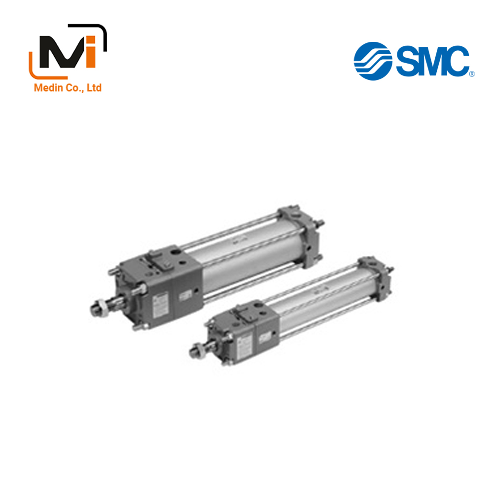
Fine Lock Cylinder, Double Acting, Single Rod CLA2 Series – Xi Lanh Khí Nén SMC
Product Description
– Xi Lanh Khí Nén SMC
A standard-type double-acting, single-rod cylinder.
[Features]
· A fine lock cylinder that locks in either direction.
· A cylinder with lock that is suitable for intermediate stops, emergency stops and drop prevention.
· D-P3DW□ Series Magnetic Field Resistant 2-Color Indicator Solid State Auto Switch is mountable.
· With auto switch (CDLA2 Series: CDLA2).
*See the SMC catalog for specification details.
*Product pictures are representative images. CAD data is not supported for some model numbers.
Download
Fine Lock Cylinder, Double Acting, Single Rod CLA2 Series Specifications – Xi Lanh Khí Nén SMC

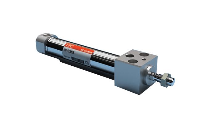
Fine Lock Cylinder, Double Acting, Single Rod CLA2 Series external appearance
| Tube Inner Diameter (mm) | 40 | 50 | 63 | 80 | 100 | 40 | 50 | 63 | 80 | 100 |
|---|---|---|---|---|---|---|---|---|---|---|
| Type | Non-lube | Air-hydro type | ||||||||
| Fluid | Air | Turbine oil (lock portion is air) | ||||||||
| Action | Double acting | |||||||||
| Proof Pressure | 1.5 MPa | |||||||||
| Maximum operating pressure | 1.0 MPa | |||||||||
| Minimum operating pressure | 0.08 MPa | 0.2 MPa | ||||||||
| Piston Speed | 50 to 500 mm/sec* | 15 to 300 mm/sec* | ||||||||
| Ambient and Working Fluid Temperature | Without auto switch: -10°C to 70°C With auto switch: -10°C to 60°C (no freezing) |
5°C to 60°C | ||||||||
| Cushioning | Air cushion | None | ||||||||
| Stroke Length Tolerance | Up to 250: (0 to +1.0), 251 to 1,000: (0 to +1.4), 1,001 to 1,500: (0 to +1.8) | |||||||||
| Mounting | Basic, axial foot, rod flange, head flange, single clevis, double clevis, center trunnion | |||||||||
*Constraints associated with the allowable kinetic energy are imposed on the speeds at which the piston can be locked.
Lock Specifications
| Locking Action | Spring locking (Exhaust Locking) |
Spring/Pneumatic Combination Lock |
Pneumatic locking (Pressure locking) |
|---|---|---|---|
| Unlocking pressure (MPa) | 0.3 or more | 0.1 or more | |
| Lock starting pressure (MPa) | 0.25 or less | 0.05 or less | |
| Maximum operating pressure MPa | 1.0 | 0.5 | |
| Locking Direction | Bidirectional | ||
*Adjust the switch position so that it operates upon movement to both the stroke end and backlash (2 mm) positions.
Standard Stroke
| Tube Inner Diameter (mm) | Standard stroke (mm)*1 | Long stroke (mm)*2 |
|---|---|---|
| 40 | 25, 50, 75, 100, 125, 150, 175, 200, 250, 300, 350, 400, 450, 500 | 800 |
| 50, 63 | 25, 50, 75, 100, 125, 150, 175, 200, 250, 300, 350, 400, 450, 500, 600 | 1,200 |
| 80, 100 | 25, 50, 75, 100, 125, 150, 175, 200, 250, 300, 350, 400, 450, 500, 600, 700 | ø80 (80-mm diameter): 1,400 ø100 (100-mm diameter): 1,500 |
*1: Consult with the manufacturer support center regarding intermediate strokes not listed above. Spacers are not used for intermediate strokes.
*2: Long stroke applies to the axial foot type and rod-end flange types.
CDLA2B40-25-D-M9BW
CDLA2B40-25-D-M9BWS
CDLA2B40-25-E
CDLA2B40-25-E-M9BL
CDLA2B40-25-P
CDLA2B40-35-E
CDLA2B40-35-E-A54
CDLA2B40-40-D
CDLA2B40-40-D-Z73L4
CDLA2B40-45-D
CDLA2B40-50-D
CDLA2B40-50-D-A543
CDLA2B40-50-E
CDLA2B40-50-P
CDLA2B40-60-E-Y59ALS
CDLA2B40-75-D
CDLA2B40-75-D-B54Z3
CDLA2B40-75-D-M9BWL
CDLA2B40-75-E
CDLA2B40-100-D
CDLA2B40-100-D-M9BW
CDLA2B40-100-E
CDLA2B40-100-P
CDLA2B40-100J-E
CDLA2B40-100N-D
CDLA2B40-100N-E
CDLA2B40-110-D
CDLA2B50-15-D-A53L
CDLA2B50-25-D
CDLA2B50-25-D-M9BW
CDLA2B50-25-E
CDLA2B50-25J-D
CDLA2B50-30-E
CDLA2B50-35-E
CDLA2B50-40-E
CDLA2B50-50-D
CDLA2B50-50-E
CDLA2B50-50-E-XC3CB
CDLA2B50-50-P
CDLA2B50-50N-D
CDLA2B50-60-E
CDLA2B50-62-E-J59WL
CDLA2B50-62-E-M9BWL
CDLA2B50-75-D
CDLA2B50-75-E
CDLA2B50-75-E-A54
CDLA2B50-75-E-A534
CDLA2B50-75-P
CDLA2B50-75JN-E
CDLA2B50-80-E
CDLA2B50-80-E-M9BA
CDLA2B50-80-E-M9BAL
CDLA2B50-80-E-Y7BAL
CDLA2B50-80-P
CDLA2B63-25-P
CDLA2B63-40-P
CDLA2B63-50-D
CDLA2B63-50-D-J59WL
CDLA2B63-50-E
CDLA2B63-50-E-A54
CDLA2B63-50-E-F59
CDLA2B63-50-E-J59W
CDLA2B63-50-E-J59WL
CDLA2B63-50-E-K59
CDLA2B63-50-E-M9B
CDLA2B63-50-E-M9BW
CDLA2B63-50-P
CDLA2B63-50-P-J59WL
CDLA2B63-50J-D
CDLA2B63-60-E-M9BW
CDLA2B63-75-D
CDLA2B63-75-D-M9B
CDLA2B63-75-D-XC6
CDLA2B63-75-E
CDLA2B63-75-E-A543
CDLA2B63-75-E-M9BL3
CDLA2B63-80-D
CDLA2B63-85-E
CDLA2B63-1000-D
CDLA2B63-1000-D-A53
CDLA2B80-25-E
CDLA2B80-25-E-M9BWL
CDLA2B80-25-P
CDLA2B80-40-D
CDLA2B80-40-E
CDLA2B80-45-D
CDLA2B80-45-D-B54Z
CDLA2B80-45-E
CDLA2B80-45K-D
CDLA2B80-50-D
CDLA2B80-50-D-M9B
CDLA2B80-50-D-M9BWL
CDLA2B100-20-E
CDLA2B100-25-D
CDLA2B100-25-D-F5PL
CDLA2B100-25-E
CDLA2B100-35-D
CDLA2B100-50-D
CDLA2B100-50-E
CDLA2B100-50N-E-M9BL
CDLA2B100-60-E
CDLA2B100-75-D
CDLA2B100-75-D-F5PL3
CDLA2B100-75-E
CDLA2B100-75-E-A54
CDLA2B100-75-P
CDLA2B100-80-D
CDLA2B100-1000-D
CDLA2B100-1000-E

