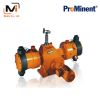

Hydraulic Diaphragm Metering Pump HYDRO Classic ProMinent
Capacity range of single-head pump: 3 – 1450 l/h, 100 – 7 bar
As an extremely robust hydraulic diaphragm metering pump, the HYDRO range meets the most exacting safety requirements.
Its modular construction, with either one or two dosing heads, 4 gear ratios, 2 dosing head sizes and 3 dosing head materials, offers a very high degree of flexibility in terms of areas of application.
Downloads

Hydraulic Diaphragm Metering Pump HYDRO Classic ProMinent
Capacity range of single-head pump: 3 – 1450 l/h, 100 – 7 bar
As an extremely robust hydraulic diaphragm metering pump, the HYDRO range meets the most exacting safety requirements.
Its modular construction, with either one or two dosing heads, 4 gear ratios, 2 dosing head sizes and 3 dosing head materials, offers a very high degree of flexibility in terms of areas of application.
For flexible metering with excellent process reliability in the medium pressure range.
The hydraulic diaphragm metering pump HYDRO with its HP2a, HP3a and HP4a product ranges forms an integrated product range with stroke lengths of 15 or 20 mm.
This covers the capacity range from 3 to 1450 l/h at 100 – 7 bar.
A wide range of power end versions is available, including some for use in areas at risk from explosion with ATEX certification.
Your benefits
Excellent process reliability:
- PTFE multi-layer diaphragm with integral diaphragm rupture warning / signalling system
- Integral hydraulic relief valve
- The dosing precision is better than ± 1 % within the 20-100 % stroke volume range under defined conditions and with correct installation
Excellent flexibility:
- The modular construction with single and double head versions permits a wide range of applications, with the double head designs (boxer principle) being operated in push-pull mode
- It is possible to combine up to 5 metering units, even with different pump capacities, in multiple pump systems
- 5 different gear ratios are available
Field of application
The following list of applications are general examples of generally suitable applications for this product.
Please contact your local sales representative to talk about the applicable use of this product in your specific case / environment.
- Oil and gas industry
- Volume-proportional metering of chemicals/additives in the treatment of boiler feed water
- Metering of reactants and catalysts in the chemical industry
- Level-dependent metering of auxiliary agents in industrial production engineering, for instance hot wax metering in the production of adhesive strips
Technical Details
- Stroke length: 15 mm (HP2a, HP3a), 20 mm (HP4a)
- Rod force: 2000 N (HP2a), 4200 N (HP3a), 5800 N (HP4a)
- Stroke volume adjustment range: 0 – 100%
- Stroke volume adjustment: manually using scaled rotary dial (optionally with electric actuator or control drive)
- The dosing precision is better than ± 1 % within the 20 to 100% stroke volume range under defined conditions and with correct installation
- PTFE multi-layer diaphragm with electrical diaphragm rupture warning / signalling system via a contact
- Integrated hydraulic relief and vent valve
- Wetted materials: PVDF, PTFE+25% carbon, stainless steel 1.4571, Hastelloy C.
- A wide range of power end/drive versions is available: Three-phase or 1-phase AC motor, motors for use in areas at risk from explosion, different flange designs for use of customer-specific motors
- Degree of protection: IP 55
Hydraulic Diaphragm Metering Pump HYDRO HP2a
Technical data for HYDRO HP2a
| Type | Capacity at max. back pressure with 1500 rpm motor at 50 Hz | Capacity at max. back pressure at 60 Hz | Suction lift | Perm. pre-pressure suction side | Suction/discharge side connector | Shipping weight | Plunger Ø | |||||
|---|---|---|---|---|---|---|---|---|---|---|---|---|
| Max. stroke rate | Max. stroke rate | |||||||||||
| l/h | bar | ml/stroke | Strokes/min | psi | l/h / gph (US) | Strokes/min | m WC | bar | G-DN | kg | mm | |
| * SST version with double ball valve, valve connector on the suction-discharge side with female thread Rp 1/4 and male thread G 3/4 – DN 10 | ||||||||||||
| ** HV design with G1 – DN 15 connector | ||||||||||||
| 100003 * | 3 | 100 | 3.0 | 60 | 1,450 | 3.6/1.0 | 72 | 3.0 | 5 | Rp 1/4 | 31 | 16 |
| 100006 * | 6 | 100 | 3.0 | 125 | 1,450 | 7.0/1.8 | 150 | 3.0 | 5 | Rp 1/4 | 31 | 16 |
| 100007 * | 7 | 100 | 3.0 | 150 | 1,450 | 8.0/2.1 | 180 | 3.0 | 5 | Rp 1/4 | 31 | 16 |
| 100009 * | 9 | 100 | 3.0 | 187 | 1,450 | 11.0/2.9 | 224 | 3.0 | 5 | Rp 1/4 | 31 | 16 |
| 100010 * | 10 | 100 | 3.0 | 212 | – | – | – | 3.0 | 5 | Rp 1/4 | 31 | 16 |
| 064007 | 7 | 64 | 3.8 | 60 | 928 | 8.4/2.2 | 72 | 3.0 | 5 | G 3/4-10 | 31 | 18 |
| 064015 | 15 | 64 | 3.8 | 125 | 928 | 18.0/4.8 | 150 | 3.0 | 5 | G 3/4-10 | 31 | 18 |
| 064018 | 18 | 64 | 3.8 | 150 | 928 | 21.0/5.5 | 180 | 3.0 | 5 | G 3/4-10 | 31 | 18 |
| 064022 | 22 | 64 | 3.8 | 187 | 928 | 26.0/6.9 | 224 | 3.0 | 5 | G 3/4-10 | 31 | 18 |
| 064025 | 25 | 64 | 3.8 | 212 | – | – | – | 3.0 | 5 | G 3/4-10 | 31 | 18 |
| 040014 | 14 | 40 | 5.7 | 60 | 580 | 16.8/4.4 | 72 | 3.0 | 5 | G 3/4-10 | 31 | 22 |
| 040029 | 29 | 40 | 5.7 | 125 | 580 | 34.8/9.2 | 150 | 3.0 | 5 | G 3/4-10 | 31 | 22 |
| 040035 | 35 | 40 | 5.7 | 150 | 580 | 42.0/11.1 | 180 | 3.0 | 5 | G 3/4-10 | 31 | 22 |
| 040044 | 44 | 40 | 5.7 | 187 | 580 | 52.8/13.9 | 224 | 3.0 | 5 | G 3/4-10 | 31 | 22 |
| 040050 | 50 | 40 | 5.7 | 212 | 580 | – | – | 3.0 | 5 | G 3/4-10 | 31 | 22 |
| 025019 ** | 19 | 25 | 7.9 | 60 | 362 | 23.0/6.1 | 72 | 3.0 | 5 | G 3/4-10 | 31 | 26 |
| 025040 ** | 40 | 25 | 7.9 | 125 | 362 | 48.0/12.7 | 150 | 3.0 | 5 | G 3/4-10 | 31 | 26 |
| 025048 ** | 48 | 25 | 7.9 | 150 | 362 | 58.0/15.3 | 180 | 3.0 | 5 | G 3/4-10 | 31 | 26 |
| 025060 ** | 60 | 25 | 7.9 | 187 | 362 | 72.0/19.0 | 224 | 3.0 | 5 | G 3/4-10 | 31 | 26 |
| 025068 ** | 68 | 25 | 7.9 | 212 | – | – | – | 3.0 | 5 | G 3/4-10 | 31 | 26 |
PVDF version max. 25 bar, PTFE + 25 % carbon; PTFE max.16 bar
Wetted materials for HYDRO HP2a
| Identity code of material | Dosing head | Connection on suction/discharge side | Seals/ball seat | Balls |
|---|---|---|---|---|
| * Not for areas at risk from explosion | ||||
| PVT * | PVDF | PVDF | PTFE/PTFE + 25 % carbon | Ceramic |
| SST | Stainless steel 1.4571/1.4404 | Stainless steel 1.4581 | PTFE/stainless steel 1.4404 | Ceramic |
| TTT | PTFE + 25% carbon | PVDF (polyvinylidene fluoride) | PTFE/PTFE + 25 % carbon | Ceramic |
| SCT | Stainless steel 316L | Stainless steel 1.4581 | PTFE/stainless steel 1.4404 | Ceramic |
Motor data for HYDRO HP2a
| Identity code specification | Power supply | Remarks | |||
| S | 3-phase, IP 55* | 230 V/400 V | 50 Hz | 0.37 kW | |
| T | 3-phase, IP 55* | 230 V/400 V 265 V/460 V |
50 Hz 60 Hz |
0.37 kW | With PTC, speed control range 1:5 |
| R | 3-phase, IP 55* | 230 V/400 V | 50 Hz | 0.45 kW | With PTC, speed control range 1:20, with external fan 1-phase 230 V; 50/60 Hz |
| V0 | 1-phase, IP 55* | 230 V | 50 Hz | 0.37 kW | Variable speed stroke control motor with integrated frequency converter |
| L2 | 3-phase, II 2G Ex de IIC T4 Gb | 230 V/400 V | 50 Hz | 0.37 kW | With PTC, speed control range 1:5 |
| P2 | 3-phase, II 2G Ex de IIC T4 | 265 V/460 V | 60 Hz | 0.37 kW | With PTC, speed control range 1:5 |
* Three-phase motor according to IEC 60034-1
Motor data sheets can be requested for more information. Versions 265/460V – 60Hz, special motors or special motor flanges are available on request.
Information for use in areas at risk from explosion
Only use pumps with the appropriate labelling in line with the ATEX Directive 2014/34/EC in premises at risk from explosion.
Ensure that the explosion group, category and degree of protection specified on the label correspond to or are superior to the conditions prevalent in the intended application.
Hydraulic Diaphragm Metering Pump HYDRO HP3a
Technical data for HYDRO HP3a
| Type | Capacity at max. back pressure with 1500 rpm motor at 50 Hz | Capacity at max. back pressure at 60 Hz | Suction lift | Perm. pre-pressure suction side | Suction/discharge side connector | Shipping weight | Plunger Ø | |||||
|---|---|---|---|---|---|---|---|---|---|---|---|---|
| Max. stroke rate | Max. stroke rate | |||||||||||
| l/h | bar | ml/stroke | Strokes/min | psi | l/h / gph (US) | Strokes/min | m WC | bar | G-DN | kg | mm | |
| * SST version with double ball valve, valve connector on the suction/discharge side with female thread Rp 3/8, male thread G 3/4-DN 10 | ||||||||||||
| ** HV design (SST only) with G 1 – DN 15 connector | ||||||||||||
| *** HV design (SST only) with 1 1/4″ – DN 20 connector | ||||||||||||
| 100010 | 10 | 100 | 5.7 | 60 | 1,450 | 12/3.2 | 72 | 3.0 | 5 | Rp 3/8-10 | 41 | 22 |
| 100021 * | 21 | 100 | 5.7 | 125 | 1,450 | 25/6.6 | 150 | 3.0 | 5 | Rp 3/8-10 | 41 | 22 |
| 100025 * | 25 | 100 | 5.7 | 150 | 1,450 | 30/7.9 | 180 | 3.0 | 5 | Rp 3/8-10 | 41 | 22 |
| 100031 * | 31 | 100 | 5.7 | 187 | 1,450 | 37/9.8 | 224 | 3.0 | 5 | Rp 3/8-10 | 41 | 22 |
| 100035 * | 35 | 100 | 5.7 | 212 | 1,450 | – | – | 3.0 | 5 | Rp 3/8-10 | 41 | 22 |
| 064019 ** | 19 | 64 | 7.9 | 60 | 928 | 23/6.1 | 72 | 3.0 | 5 | G 3/4-10 | 41 | 26 |
| 064040 ** | 40 | 64 | 7.9 | 125 | 928 | 48/12.7 | 150 | 3.0 | 5 | G 3/4-10 | 41 | 26 |
| 064048 ** | 48 | 64 | 7.9 | 150 | 928 | 58/15.3 | 180 | 3.0 | 5 | G 3/4-10 | 41 | 26 |
| 064060 ** | 60 | 64 | 7.9 | 187 | 928 | 72/19.0 | 224 | 3.0 | 5 | G 3/4-10 | 41 | 26 |
| 064068 ** | 68 | 64 | 7.9 | 212 | 928 | – | – | 3.0 | 5 | G 3/4-10 | 41 | 26 |
| 040029 *** | 29 | 40 | 12.0 | 60 | 580 | 35/9.2 | 72 | 3.0 | 5 | G 1-15 | 41 | 32 |
| 040062 *** | 62 | 40 | 12.0 | 125 | 580 | 74/19.7 | 150 | 3.0 | 5 | G 1-15 | 41 | 32 |
| 040074 *** | 74 | 40 | 12.0 | 150 | 580 | 89/23.5 | 180 | 3.0 | 5 | G 1-15 | 41 | 32 |
| 040092 *** | 92 | 40 | 12.0 | 187 | 580 | 110/29.2 | 224 | 3.0 | 5 | G 1-15 | 41 | 32 |
| 040105 *** | 105 | 40 | 12.0 | 212 | 580 | – | – | 3.0 | 5 | G 1-15 | 41 | 32 |
| 025048 *** | 48 | 25 | 17.0 | 60 | 362 | 58/15.3 | 72 | 3.0 | 5 | G 1-15 | 41 | 38 |
| 025100 *** | 100 | 25 | 17.0 | 125 | 362 | 120/31.7 | 150 | 3.0 | 5 | G 1-15 | 41 | 38 |
| 025120 *** | 120 | 25 | 17.0 | 150 | 362 | 144/38.0 | 180 | 3.0 | 5 | G 1-15 | 41 | 38 |
| 025150 *** | 150 | 25 | 17.0 | 187 | 362 | 180/47.6 | 224 | 3.0 | 5 | G 1-15 | 41 | 38 |
| 025170 *** | 170 | 25 | 17.0 | 212 | 362 | – | – | 3.0 | 5 | G 1-15 | 41 | 38 |
PVDF version max. 25 bar, PTFE + 25 % carbon; PTFE max.16 bar
SST version with double ball valve, valve connector on the suction/discharge side with female thread Rp 3/8, male thread G 3/4-DN 10
Wetted materials for HYDRO HP3a
| Identity code of material | Dosing head | Connection on suction/discharge side | Seals/ball seat | Balls |
|---|---|---|---|---|
| * Not for areas at risk from explosion | ||||
| PVT * | PVDF | PVDF | PTFE/PTFE + 25 % carbon | Ceramic |
| SST | Stainless steel 1.4571/1.4404 | Stainless steel 1.4581 | PTFE/ZrO2 (DN 15/DN20 stainless steel 1.4404) | Ceramic |
| TTT | PTFE + 25% carbon | PVDF (polyvinylidene fluoride) | PTFE/PTFE + 25 % carbon | Ceramic |
| SCT | Stainless steel 316L | Stainless steel 1.4581 | PTFE/stainless steel 1.4404 | Ceramic |
Motor data for HYDRO HP3a
| Identity code specification | Power supply | Remarks | |||
| S | 3-phase, IP 55* | 230 V/400 V | 50 Hz | 0.75 kW | |
| T | 3-phase, IP 55* | 230 V/400 V 265 V/460 V |
50 Hz 60 Hz |
0.75 kW | With PTC, speed control range 1:5 |
| R | 3-phase, IP 55* | 230 V/400 V | 50 Hz | 0.75 kW | With PTC, speed control range 1:20, with external fan 1-phase 230 V; 50/60 Hz |
| V0 | 1-phase, IP 55* | 230 V | 50 Hz | 0.75 kW | Variable speed stroke control motor with integrated frequency converter |
| L2 | 3-phase, II 2G Ex de IIC T4 | 230 V/400 V | 50 Hz | 0.75 kW | With PTC, speed control range 1:5 |
| P2 | 3-phase, II 2G Ex de IIC T4 | 265 V/460 V | 60 Hz | 0.75 kW | With PTC, speed control range 1:5 |
* 3-phase AC motor in accordance with IEC 60034-1
Motor data sheets can be requested for more information. 265/460V – 60Hz versions, special motors or special motor flanges are available on request.
Information for use in areas at risk from explosion
Only use pumps with the appropriate labelling in line with the ATEX Directive 2014/34/EC in premises at risk from explosion.
Ensure that the explosion group, category and degree of protection specified on the label correspond to or are superior to the conditions prevalent in the intended application.
Hydraulic Diaphragm Metering Pump HYDRO HP4a
Technical data for HYDRO HP4a
| Type | Capacity at max. back pressure with 1500 rpm motor at 50 Hz | Capacity at max. back pressure at 60 Hz | Suction lift | Perm. pre-pressure suction side | Suction/discharge side connector | Shipping weight | Plunger Ø | |||||
|---|---|---|---|---|---|---|---|---|---|---|---|---|
| Max. stroke rate | Max. stroke rate | |||||||||||
| l/h | bar | ml/stroke | Strokes/min | psi | l/h / gph (US) | Strokes/min | m WC | bar | G-DN | kg | mm | |
| 400071 | 71 | 40 | 25.1 | 71 | 580 | 85/22 | 86 | 3 | 5 | G 1-15 | 69 | 40 |
| 400105 | 105 | 40 | 25.1 | 103 | 580 | 126/33 | 124 | 3 | 5 | G 1-15 | 69 | 40 |
| 400140 | 140 | 40 | 25.1 | 136 | 580 | 168/44 | 164 | 3 | 5 | G 1-15 | 69 | 40 |
| 400190 | 190 | 40 | 25.1 | 188 | 580 | 188/49 | 225 | 3 | 5 | G 1-15 | 69 | 40 |
| 400220 | 220 | 40 | 25.1 | 214 | 580 | – | – | 3 | 5 | G 1-15 | 69 | 40 |
| 250130 | 130 | 25 | 42.4 | 71 | 363 | 155/41 | 86 | 3 | 5 | G 1 1/2-25 | 69 | 52 |
| 250190 | 190 | 25 | 42.4 | 103 | 363 | 230/61 | 124 | 3 | 5 | G 1 1/2-25 | 69 | 52 |
| 250250 | 250 | 25 | 42.4 | 136 | 363 | 300/79 | 164 | 3 | 5 | G 1 1/2-25 | 69 | 52 |
| 250350 | 350 | 25 | 42.4 | 188 | 363 | 420/111 | 225 | 3 | 5 | G 1 1/2-25 | 69 | 52 |
| 250400 | 400 | 25 | 42.4 | 214 | – | – | – | 3 | 5 | G 1 1/2-25 | 69 | 52 |
| 160210 | 210 | 16 | 62.3 | 71 | 232 | 250/66 | 86 | 3 | 5 | G 1 1/2-25 | 76 | 63 |
| 160300 | 300 | 16 | 62.3 | 103 | 232 | 360/95 | 124 | 3 | 5 | G 1 1/2-25 | 76 | 63 |
| 160400 | 400 | 16 | 62.3 | 136 | 232 | 480/127 | 164 | 3 | 5 | G 1 1/2-25 | 76 | 63 |
| 160550 | 550 | 16 | 62.3 | 188 | 232 | 660/174 | 225 | 3 | 5 | G 1 1/2-25 | 76 | 63 |
| 160625 | 625 | 16 | 62.3 | 214 | – | – | – | 3 | 5 | G 1 1/2-25 | 76 | 63 |
| 100330 | 330 | 10 | 100.4 | 71 | 145 | 400/106 | 86 | 3 | 5 | G 2-32 | 87 | 80 |
| 100480 | 480 | 10 | 100.4 | 103 | 145 | 580/153 | 124 | 3 | 5 | G 2-32 | 87 | 80 |
| 100635 | 635 | 10 | 100.4 | 136 | 145 | 760/201 | 164 | 3 | 5 | G 2-32 | 87 | 80 |
| 100880 | 880 | 10 | 100.4 | 188 | 145 | 1,050/277 | 225 | 3 | 5 | G 2-32 | 87 | 80 |
| 101000 | 1,000 | 10 | 100.4 | 214 | – | – | – | 3 | 5 | G 2-32 | 87 | 80 |
| 070465 | 465 | 7 | 138.7 | 71 | 102 | 560/148 | 86 | 3 | 5 | G 2 1/4-40 | 96 | 94 |
| 070670 | 670 | 7 | 138.7 | 103 | 102 | 805/213 | 124 | 3 | 5 | G 2 1/4-40 | 96 | 94 |
| 070890 | 890 | 7 | 138.7 | 136 | 102 | 1,070/283 | 164 | 3 | 5 | G 2 1/4-40 | 96 | 94 |
| 071230 | 1,230 | 7 | 138.7 | 188 | 102 | 1,450/383 | 225 | 3 | 5 | G 2 1/4-40 | 96 | 94 |
| 071400 | 1,400 | 7 | 138.7 | 214 | – | – | – | 3 | 5 | G 2 1/4-40 | 96 | 94 |
PVDF version max. 25 bar, PTFE + 25 % carbon; PTFE max.10 bar
Wetted materials for HYDRO HP4a
| Identity code of material | Dosing head | Connection on suction/discharge side | Seals | Valve seats | Valve balls up to DN 25 | Valve plates/valve springs |
|---|---|---|---|---|---|---|
| * Not for areas at risk from explosion | ||||||
| SCT | Stainless steel 316L | Stainless steel 1.4581 | PTFE | Stainless steel 1.4404 | Ceramic | Stainless steel 1.4404/Hastelloy C |
| PVT * | PVDF | PVDF | PTFE | PTFE + 25% carbon | Glass | Ceramic/E-CTFE |
| SST | Stainless steel 1.4404 | Stainless steel 1.4404 | PTFE | PTFE | Stainless steel 1.4401 | Stainless steel 1.4404/Hastelloy C |
| TTT | PTFE + 25% carbon | PVDF (polyvinylidene fluoride) | PTFE | PTFE + 25% carbon | Glass | Ceramic/E-CTFE |
Motor data for HYDRO HP4a
| Identity code specification | Power supply | Remarks | |||
| S | 3-phase, IP 55* | 230 V/400 V | 50 Hz | 1.1 kW | |
| T | 3-phase, IP 55* | 230 V/400 V 265 V/460 V |
50 Hz 60 Hz |
1.1 kW | With PTC, speed control range 1:5 |
| R | 3-phase, IP 55* | 230 V/400 V | 50 Hz | 1.5 kW | With PTC, speed control range 1:20, with external fan 1-phase 230 V; 50/60 Hz |
| V0 | 3-phase, IP 55* | 400 V | 50 Hz | 1.5 kW | Variable speed stroke control motor with integrated frequency converter |
| L2 | 3-phase, II 2G Ex de IIC T4 Gb | 230 V/400 V | 50 Hz | 1.1 kW | With PTC, speed control range 1:5 |
| P2 | 3-phase, II 2G Ex de IIC T4 | 265 V/460 V | 60 Hz | 1.1 kW | With PTC, speed control range 1:5 |
* 3-phase AC motor in accordance with IEC 60034-1
Motor data sheets can be requested for more information. 265/460V – 60Hz versions, special motors or special motor flanges are available on request.
Information for use in areas at risk from explosion
Only use pumps with the appropriate labelling in line with the ATEX Directive 2014/34/EC in premises at risk from explosion.
Ensure that the explosion group, category and degree of protection specified on the label correspond to or are superior to the conditions prevalent in the intended application.
Tại Sao Chọn Medin Company?
Medin Company chuyên cung cấp các sản phẩm chính hãng chất lượng cao.
Với kinh nghiệm sâu rộng trong ngành, chúng tôi không chỉ cung cấp sản phẩm mà với đội ngũ kĩ sư giàu kinh nghiệm, chúng tôi còn mang đến giải pháp tối ưu cho khách hàng.
Medin Company đảm bảo:
- Sản phẩm chính hãng 100%
- Giá cả cạnh tranh nhất thị trường
- Bảo hành chính hãng toàn cầu
Dịch Vụ Dùng Thử Miễn Phí
- Test tại nhà máy khách hàng: Đánh giá hiệu suất thực tế
- Không phí phát sinh: Miễn phí hoàn toàn trong 30 ngày
- Cam kết hiệu quả: Đảm bảo tăng productivity tối thiểu 30%
Khảo Sát Tận Nơi
- Site survey chuyên nghiệp: Kỹ sư senior trực tiếp khảo sát
- Báo cáo chi tiết: Phân tích toàn diện điều kiện vận hành
- Tư vấn tối ưu: Giải pháp phù hợp 100% với nhu cầu
Hỗ Trợ Kỹ Thuật 24/7
- Hotline chuyên dụng: Phản hồi trong 15 phút
- Remote support: Hỗ trợ từ xa qua
- On-site service: Kỹ sư đến tận nơi trong 24h
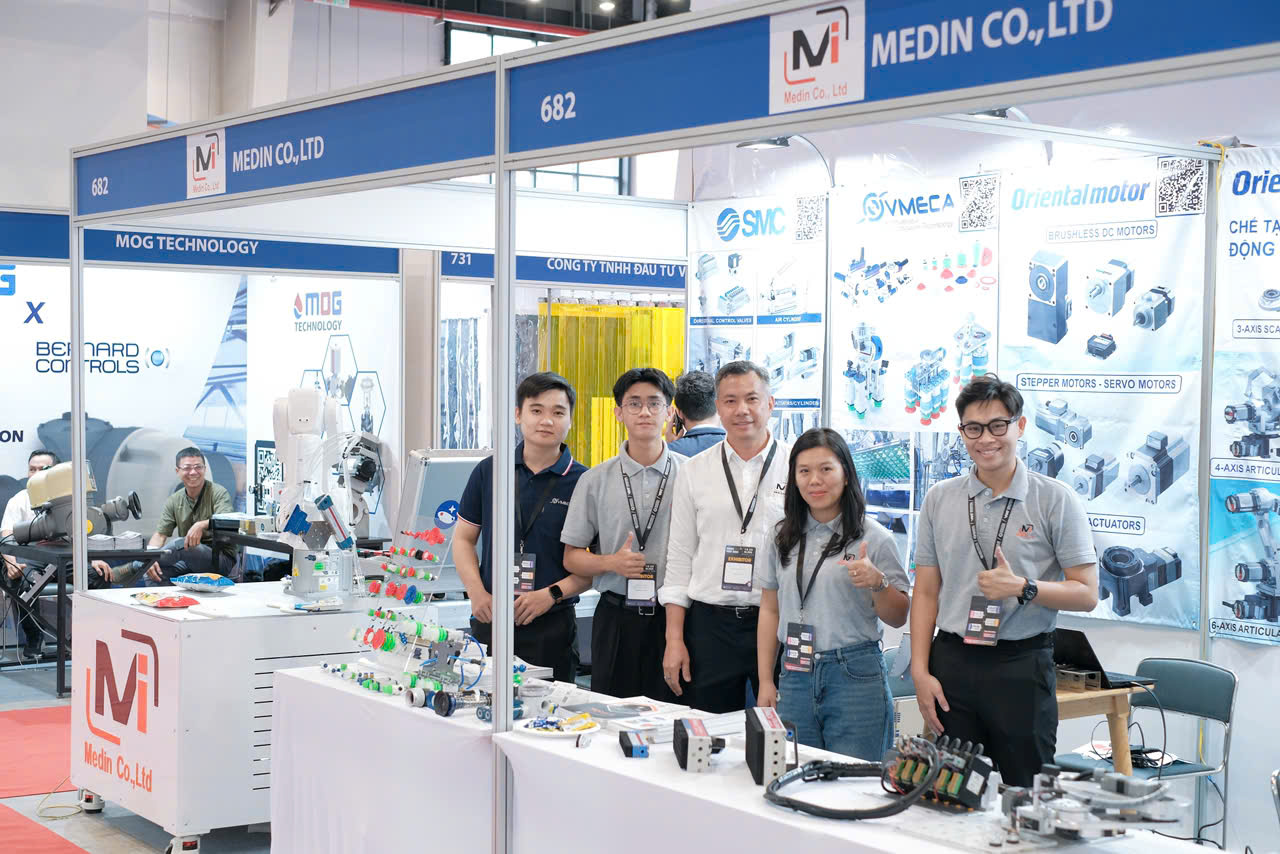
Liên Hệ Medin Co., Ltd
- Công ty TNHH Mễ Đình được thành lập từ năm 2006.
- Từ đó đến nay Medin luôn là Công ty dẫn đầu về lĩnh vực Tự Động Hoá ở thị trường trong và ngoài nước với hơn 1,000 khách hàng, cùng với rất nhiều dự án lớn nhỏ cho các nhà máy sản xuất.
- Chúng tôi cung cấp cho khách hàng những giải phát tuyệt vời nhất trong việc ứng dụng Tự Động Hoá vào sản xuất
- Phương châm: “Giải pháp của chúng tôi, lợi ích của khách hàng”
- Giá trị cốt lõi: “Uy tín là sự tồn tại của chúng tôi”
![]()
- Hơn 20 năm kinh nghiệm, chúng tôi có đội ngũ kỹ sư nhiều kinh nghiệm, có khả năng tư vấn, đưa ra giải pháp có lợi nhất cho khách hàng.
- Sự tin tưởng và đồng hành của khách hàng là động lực để Medin phát triển cao hơn và xa hơn.