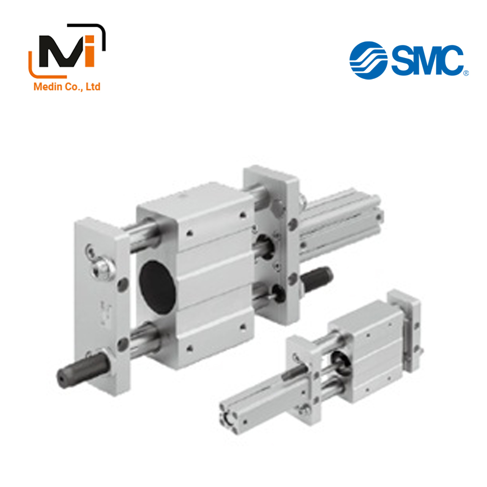
CXT Series Platform Cylinder– Xi Lanh Khí Nén SMC
Product Description
– Xi Lanh Khí Nén SMC
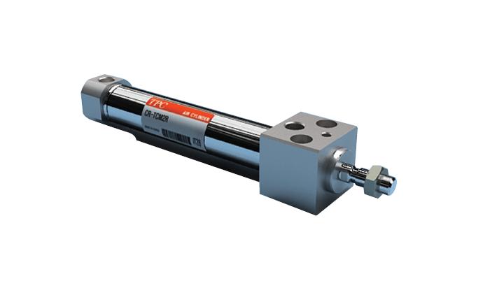
The CXT Series Platform Cylinder integrates a slide table with an actuator.
[Features]
· A slide table with high rigidity and high precision.
· Adjustment bolt with bumper is equipped as standard.
· Allows for auto switches to be mounted.
· Can be mounted on 2 sides (top and bottom).
Danh mục: AUTOMATION, Cylinders With Guides - Xi Lanh Khí Nén SMC, SMC
Download
CXT Series Platform Cylinder Specifications– Xi Lanh Khí Nén SMC
Model Number Notation
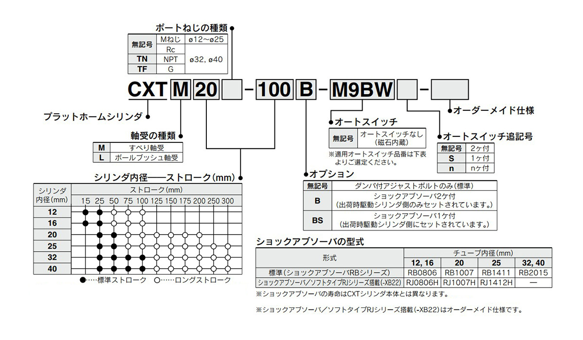
How to order: image
Applicable Auto Switches
| Type | Special Functions | Electrical Entry | Indicator Light | Wiring (Output) | Load Voltage | Auto switch unit part number | Lead Wire Length (m) | Pre-Wired Connector | Applicable Load | ||||||||
|---|---|---|---|---|---|---|---|---|---|---|---|---|---|---|---|---|---|
| DC | AC | Perpendicular | In-Line | 0.5 (Nil) |
1 (M) | 3 (L) | 5 (Z) | – (N) | |||||||||
| Solid State Auto Switch | – | Grommet | Yes | 3-wire (NPN) | 24 V | 5 V, 12 V | – | M9NV | M9NW | ● | ● | ● | ○ | – | ○ | IC circuit | Relay, PLC |
| 3-wire (PNP) | M9PV | M9P | ● | ● | ● | ○ | – | ○ | |||||||||
| 2-wire | 12 V | M9BV | M9B | ● | ● | ● | ○ | – | ○ | – | |||||||
| Diagnostic indication (2-color indicator) | 3-wire (NPN) | 5 V, 12 V | M9NWV | M9NW | ● | ● | ● | ○ | – | ○ | IC circuit | ||||||
| 3-wire (PNP) | M9PWV | M9PW | ● | ● | ● | ○ | – | ○ | |||||||||
| 2-wire | 12 V | M9BWV | M9BW | ● | ● | ● | ○ | – | ○ | – | |||||||
| Improved water resistance product (2-color indicator) | 3-wire (NPN) | 5 V, 12 V | *1M9NAV | *1M9NA | ○ | ○ | ● | ○ | – | ○ | IC circuit | ||||||
| 3-wire (PNP) | *1M9PAV | *1M9PA | ○ | ○ | ● | ○ | – | ○ | |||||||||
| 2-wire | 12 V | *1M9BAV | *1M9BA | ○ | ○ | ● | ○ | – | ○ | – | |||||||
| Magnetic field resistant (2-color indication) | 2-wire (non-polar) | – | – | P3DWA | ● | – | ● | ● | – | ○ | |||||||
| Reed auto switch | – | Grommet | Yes | 3-wire (NPN equivalent) | – | 5 V | – | A96V | A96 | ● | – | ● | – | – | – | IC circuit | – |
| 2-wire | 24 V | 12 V | 100 V | *2A93V | A93 | ● | ● | ● | ● | – | – | – | Relay, PLC | ||||
| No | 5 V, 12 V | 100 V or less | A90V | A90 | ● | – | ● | – | – | – | IC circuit | ||||||
- *1 Water resistant type auto switches can be mounted on the above models, but in this case, the water resistance cannot be guaranteed.
Check with the manufacturer regarding water-resistant types for the above model numbers. - *2 The type with a 1 m lead wire only supports D-A93.
Individual Made-to-Order Specifications
| Symbols | Specifications/contents |
|---|---|
| -X138 | Adjustable stroke |
| -X777 | Fluoroelastomer seals (actuating cylinder unit only) |
Made to Order Specifications
| Symbols | Specifications/contents |
|---|---|
| -XB13 | Low-speed cylinder (5 to 50 mm/s) |
| -XB22 | With shock absorber, soft type RJ Series |
Specifications Table
| Tube inner diameter | 12 | 16 | 20 | 25 | 32 | 40 |
|---|---|---|---|---|---|---|
| Fluid | Air | |||||
| Action | Double-acting type | |||||
| Proof Pressure | 1.5 MPa | |||||
| Maximum operating pressure | 0.7 MPa*1 | |||||
| Minimum operating pressure | 0.15 MPa | |||||
| Ambient and Working Fluid Temperature | -10°C to 60°C (no freezing) | |||||
| Piston Speed | 50 to 500 mm/s | |||||
| Cushioning | Bumper (both sides / standard), shock absorber (option) | |||||
| Lubrication | Not required (non-lubricated) | |||||
| Stroke adjustable range | -10 mm (forward end, backward end: -5 mm each) | |||||
- *1: Maximum operating pressure for this product with the bumper feature.
The maximum operating pressure for the cylinder alone is 1 MPa.
Diagram
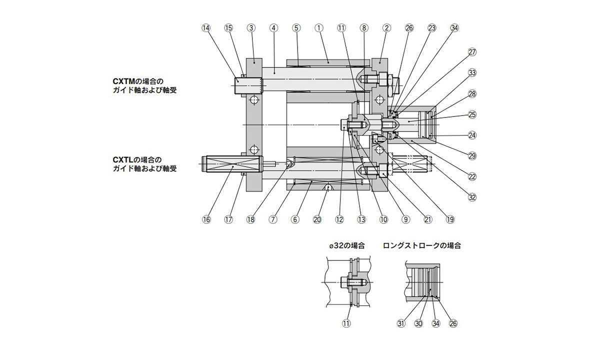
Diagram: CXT Series Platform Cylinder
Components
| Number | Part Name | Material | Notes | |
|---|---|---|---|---|
| 1 | Slide block | Aluminum alloy | Anodized aluminum | |
| 2 | Plate A | Aluminum alloy | Anodized aluminum | |
| 3 | Plate B | Aluminum alloy | Anodized aluminum | |
| 4 | Guide rod | Carbon steel | Hard chrome plating | |
| 5 | Slide Bearing | Resin/Copper alloy (Multiple layers) | – | |
| 6 | Ball Bushing Bearing | – | – | |
| 7 | Type C retaining ring | Carbon tool steel | Phosphate coating | |
| 8 | Adapter | Carbon steel | Electroless nickel plating | |
| 9 | Connected disk | Carbon steel | Electroless nickel plating | |
| 10 | Washer | Carbon steel | Zinc chromate | |
| 11 | Type C retaining ring | Carbon tool steel | Phosphate coating | |
| 12 | Hex Socket Head Cap Screw | Carbon steel | Zinc chromate | |
| 13 | Spring Washer | Steel wire | Zinc chromate | |
| 14 | Adjusting bolt (with bumper) | Carbon steel, urethane | Zinc chromate | |
| 15 | Nut | Carbon steel | Zinc chromate | |
| 16 | Shock absorber | – | Option | |
| 17 | Nut | Carbon steel | Zinc chromate | |
| 18 | Parallel pin | Carbon steel | – | |
| 19 | Hex Socket Head Cap Screw | Carbon steel | Zinc chromate | |
| 20 | Grease nipple | – | ø16 (16-mm diameter) to ø40 (40-mm diameter) | Nickel plated |
| 21 | Hex Socket Head Cap Screw | Carbon steel | Zinc chromate | |
| 22 | Cylinder Tube | Aluminum alloy | Hard anodized aluminum | |
| 23 | Collar | Aluminum alloy | Anodized aluminum | |
| 24 | Piston | Aluminum alloy | Chromate | |
| 25 | Piston rod | Stainless steel | ø12 (12‑mm diameter), ø25 (25‑mm diameter) | – |
| Carbon steel | ø32 (32-mm diameter), ø40 (40-mm diameter) | Hard chrome plating | ||
| 26 | Type C retaining ring | Carbon tool steel | Phosphate coating | |
| 27 | Bumper A | Urethane | – | |
| 28 | Damper B | Urethane | – | |
| 29 | Magnet | – | – | |
| 30 | Bottom Plate | Aluminum alloy | Anodized aluminum | |
| 31 | Wear ring | Resin | – | |
| 32 | Rod packing | NBR | – | |
| 33 | Piston packing | NBR | – | |
| 34 | Tube gasket | NBR | – | |
Dimensions: CXT Series Platform Cylinder
ø12 (12-mm bore size) to ø25 (25-mm bore size)
(Units: mm)
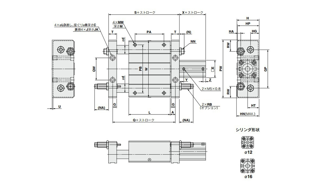
Dimensional drawings: ø12 (12-mm bore size) to ø25 (25-mm bore size)
| Bore size (mm) |
Standard Stroke (mm) |
A | B | C | d | E | G | GP | H | HA | HG | HN | HP | HT | J | JK | L | LD | |
|---|---|---|---|---|---|---|---|---|---|---|---|---|---|---|---|---|---|---|---|
| Slide | Ball bushing | ||||||||||||||||||
| 12 | 15, 25 | 8.5 | 8 | 4 | 16 | 10 | 25 | 7.5 | 50 | 34 | 6 | 14.5 | 34 | 33 | 18 | M5 × 0.8 | 9.5 | 68 | 4.3 |
| 16 | 15, 25 | 7.5 | 9.5 | 5 | 18 | 12 | 29 | 6.5 | 65 | 40 | 6.5 | 16 | 39.5 | 39 | 21 | M6 × 1 | 9.5 | 75 | 5.2 |
| 20 | 25, 50 | 9.5 | 11 | 6.5 | 25 | 16 | 36 | 8.5 | 80 | 46 | 9 | 18 | 44.1 | 45 | 24 | M8 × 1.25 | 10 | 86 | 6.9 |
| 25 | 25, 50 | 9.5 | 11 | 6.5 | 25 | 16 | 40 | 8.5 | 90 | 54 | 9 | 23 | 55 | 53 | 28 | M8 × 1.25 | 10 | 86 | 6.9 |
| Bore size (mm) | MM | M | (N) | (NA) | NN | PA* | PB | PW | Q | QW | RB | RW | S | T | U | W | X | Y | Z |
|---|---|---|---|---|---|---|---|---|---|---|---|---|---|---|---|---|---|---|---|
| 12 | M4 × 0.7 | 6 | 8 | 27 | M8 × 1.0 | 30 | 60 | 80 | 85 | 26 | RB0806 | 17.5 | 96 | 13 | 1 | 77 | 22 | 7.5 | 5 |
| 16 | M5 × 0.8 | 8 | 8 | 27 | M8 × 1.0 | 45 | 70 | 95 | 90 | 40 | RB0806 | 15 | 103 | 13 | 2 | 92 | 22 | 7.5 | 5 |
| 20 | M6 × 1 | 10 | 10 | 29 | M10 × 1.0 | 60 | 100 | 120 | 105 | 46 | RB1007 | 26 | 122 | 17 | 2 | 117 | 29.5 | 8 | 5.5 |
| 25 | M6 × 1 | 10 | 12 | 50 | M14 × 1.5 | 60 | 100 | 130 | 105 | 50 | RB1411 | 22 | 122 | 17 | 2 | 127 | 32.5 | 9 | 5.5 |
- *The PA dimension is the center sorted factor of the L dimension.
Long Stroke
(Units: mm)
| Bore size (mm) | Stroke range (mm) | X | Y | Z |
|---|---|---|---|---|
| 12 | 50, 75, 100 | 32 | 7.5 | 7.5 |
| 16 | 50, 75, 100 | 32 | 7.5 | 7.5 |
| 20 | 75, 100, 125, 150, 175, 200 | 41 | 8 | 8 |
| 25 | 75, 100, 125, 150, 175, 200, 250, 300 | 44 | 9 | 9 |
ø32 (32-mm bore size), ø40 (40-mm bore size)
(Units: mm)
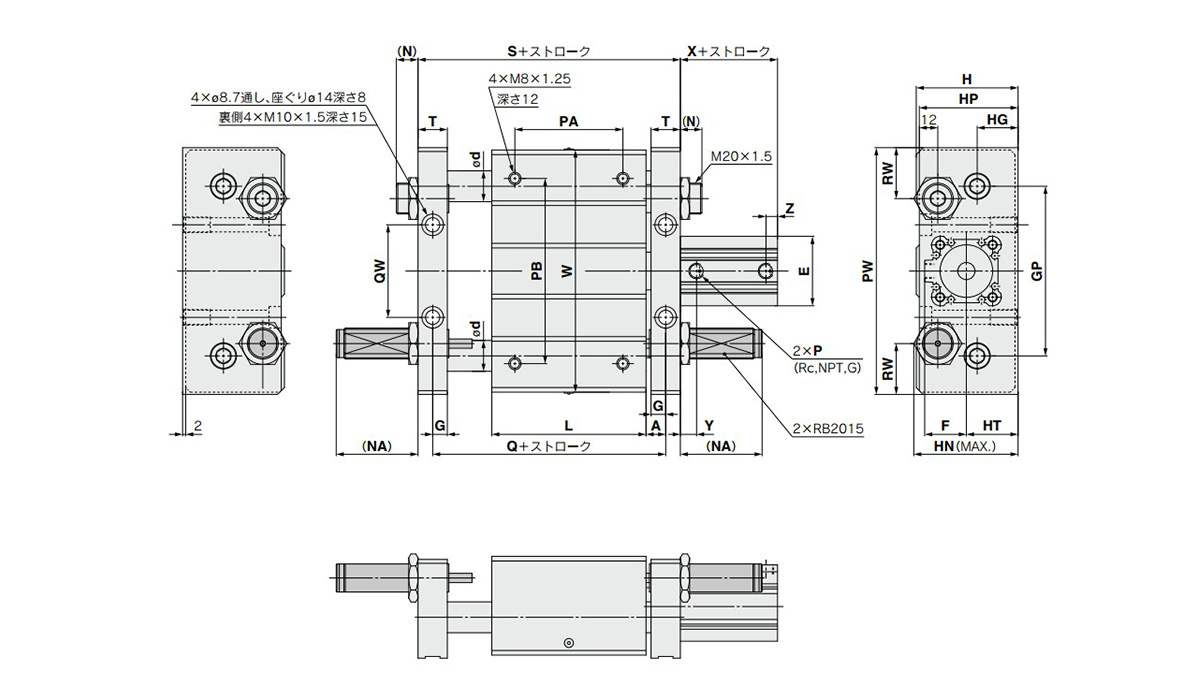
Dimensional drawings: ø32 (32-mm bore size), ø40 (40-mm bore size)
| Cylinder Internal Diameter (mm) |
Standard Stroke (mm) |
A | d | E | F | G | GP | H | HG | HN | HP | HT | L | (N) | (NA) | P*1 | PA*2 | PB | PW | Q | |
|---|---|---|---|---|---|---|---|---|---|---|---|---|---|---|---|---|---|---|---|---|---|
| Slide | Ball bushing | ||||||||||||||||||||
| 32 | 25, 50, 75, 100 | 10.5 | 28 | 20 | 45 | 27 | 9.5 | 110 | 66 | 26.5 | 67.6 | 64 | 33.5 | 100 | 14 | 53 | 1/8 | 70 | 120 | 160 | 121 |
| 40 | 25, 50, 75, 100 | 11.5 | 36 | 25 | 52 | 31 | 10.5 | 130 | 78 | 30.5 | 77.6 | 74 | 40.5 | 136 | 12 | 51 | 1/8 | 90 | 140 | 190 | 159 |
| Cylinder Inner Diameter (mm) | QW | RW | S | T | W | X | Y | Z |
|---|---|---|---|---|---|---|---|---|
| 32 | 60 | 33 | 140 | 19 | 157 | 33 | 10 | 7.5 |
| 40 | 84 | 35 | 180 | 21 | 187 | 39.5 | 12.5 | 7.5 |
- *The PA dimension is the center sorted factor of the L dimension.
- *1: Rc, NPT and G ports can be selected.
Long Stroke
(Units: mm)
| Cylinder Inner Diameter (mm) | Stroke range (mm) | X | Y | Z |
|---|---|---|---|---|
| 32 | 125, 150, 175, 200, 250, 300 | 45.5 | 10 | 10 |
| 40 | 125, 150, 175, 200, 250, 300 | 55 | 12.5 | 12.5 |
Basic Information
| Cylinder Operation Method | Double Acting | Rod Operation Method | Single Rods | Main Body Shape | Guided |
|---|---|---|---|---|---|
| Cushion | With bumper on both ends | Operating Pressure(MPa) | 0.15 to 0.7 | Specifications | Built-in magnet |
CXTL12-15
CXTL12-15-A90
CXTL12-15-A90L
CXTL12-15-A90LS
CXTL12-15-A90S
CXTL12-15-A90V
CXTL12-15-A90VL
CXTL12-15-A90VLS
CXTL12-15-A90VS
CXTL12-15-A93
CXTL12-15-A93L
CXTL12-15-A93LS
CXTL16-15
CXTL16-15-A90
CXTL16-15-A90L
CXTL16-15-A90LS
CXTL16-15-A90S
CXTL16-15-A90V
CXTL16-15-A90VL
CXTL16-15-A90VLS
CXTL16-15-A90VS
CXTL20-25
CXTL20-25-A90
CXTL20-25-A90L
CXTL20-25-A90LS
CXTL20-25-A90S
CXTL20-25-A90V
CXTL20-25-A90VL
CXTL20-25-A90VLS
CXTL20-25-A90VS
CXTL20-25-A93
CXTL25-25
CXTL25-25-A90
CXTL25-25-A90L
CXTL25-25-A90LS
CXTL25-25-A90S
CXTL25-25-A90V
CXTL25-25-A90VL
CXTL25-25-A90VLS
CXTL25-25-A90VS
CXTL25-25-A93
CXTL25-25-A93L
CXTL32-25
CXTL32-25-A73L
CXTL32-25-A79W
CXTL32-25-A90
CXTL32-25-A90L
CXTL32-25-A90LS
CXTL32-25-A90S
CXTL32-25-A90V
CXTL32-25-A90VL
CXTL32-25-A90VLS
CXTL40-25
CXTL40-25-A73
CXTL40-25-A90
CXTL40-25-A90L
CXTL40-25-A90LS
CXTL40-25-A90S
CXTL40-25-A90V
CXTL40-25-A90VL
CXTL40-25-A90VLS
CXTL40-25-A90VS
CXTL32-25-A73L
CXTL32-25-A79W
CXTL32-25-A90
CXTL32-25-A90L
CXTL32-25-A90LS
CXTL32-25-A90S
CXTL32-25-A90V
CXTL32-25-A90VL
CXTL32-25-A90VLS
CXTL40-25
CXTL40-25-A73
CXTL40-25-A90
CXTL40-25-A90L
CXTL40-25-A90LS
CXTL40-25-A90S
CXTL40-25-A90V
CXTL40-25-A90VL
CXTL40-25-A90VLS
CXTL40-25-A90VS
