


Xi Lanh Khí Nén SMC CU Series CDU20 CDU25 CDU32
CU Series Free Mount Cylinder With Air Cushion
Air cylinder that adopts a new air cushion mechanism.
Download

Xi Lanh Khí Nén SMC CU Series CDU20 CDU25 CDU32
CU Series Free Mount Cylinder With Air Cushion
[Features] · Multiple-surface direct mounting with a square body and no brackets lets you freely choose the mounting surface.· This enables space-saving designs for equipment.
· Slightly extended dimensions relative to the CU standard models.
· There is no protrusion of the cushion valve, and the width is the same.
· 3 types of mounting orientations can be accommodated according to the installation conditions.
· Approximately 2.4 times more allowable kinetic energy.
· Improved sound insulation (reduced impact of noise at the stroke end).
· Interchangeable mounting.
| Model | Pneumatic (non-lube) type |
|---|---|
| Fluid | Air |
| Proof Pressure | 1.0 MPa |
| Maximum operating pressure | 0.7 MPa |
| Minimum operating pressure | 0.08 MPa |
| Ambient and Fluid Temperature | Without auto switch: -10°C to +70 ℃ (no freezing) |
| With auto switch: -10°C to +60 ℃ (no freezing) | |
| Rod-end thread | Male thread |
| Stroke Length Tolerance | 0 to +1.0 |
| Operating piston speed | 50 to 500 mm/s |
Effective Cushion Length
- Bore size 20 mm: effective cushion length 6.6 mm
- Bore size 25 mm: effective cushion length 6.7 mm
- Bore size 32 mm: effective cushion length 7.7 mm
Standard Stroke Table
Bore size 20 mm, 25 mm, 32 mm: standard stroke 20 mm, 30 mm, 40 mm, 50 mm, 60 mm, 70 mm, 80 mm, 90 mm, 100 mm
Diagram
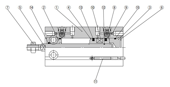
Diagram: CU Series
| Number | Part Name | Material | Quantity | Notes |
|---|---|---|---|---|
| 1 | Cylinder Tube | Aluminum alloy | 1 | Hard anodized aluminum |
| 2 | Rod cover | Aluminum alloy | 1 | Hard anodized aluminum |
| 3 | Head cover | Aluminum alloy | 1 | Chromate |
| 4 | Piston | Aluminum alloy | 1 | Chromate |
| 5 | Piston rod | Stainless steel | 1 | – |
| 6 | Retaining Ring | Carbon tool steel | 1 | Phosphate conversion coating |
| 7 | Rod end nut | Carbon steel | 1 | Chromate |
| 8 | Cushion needle assembly | – | (2) | – |
| 9 | Steel ball | Carbon steel | 2 | – |
| 10 | Magnet | – | 1 | – |
| 11 | Auto switch | – | (2) | – |
| 12 | Piston gasket | NBR | 1 | – |
| 13 | Piston packing | NBR | 2 | – |
| 14 | Rod packing | NBR | 1 | – |
| 15 | Gasket | NBR | 1 | – |
Drawing
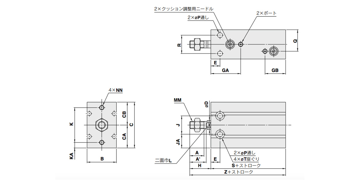
Dimensional drawings: CU Series Free Mount Cylinder With Air Cushion
(Units: mm)
| Tube inner diameter (mm) |
Port | A | A’ | B | C | CA | CB | D | E | GA | GB | H | J | JA |
|---|---|---|---|---|---|---|---|---|---|---|---|---|---|---|
| 20 | M5 × 0.8 | 12 | 14 | 26 | 42 | 20 | 22 | 8 | 9 | 29 | 27 | 19 | 16 | 12 |
| 25 | M5 × 0.8 | 15.5 | 18 | 32 | 50 | 25 | 25 | 10 | 10 | 32.5 | 22.5 | 23 | 20 | 15 |
| 32 | 1/8 | 19.5 | 22 | 40 | 62 | 31 | 31 | 12 | 11 | 35 | 25 | 27 | 24 | 19 |
(Units: mm)
| Tube inner diameter (mm) |
K | KA | L | MM | NN | P | Q | R | T | S | Z | Standard Stroke |
|---|---|---|---|---|---|---|---|---|---|---|---|---|
| 20 | 30 | 5 | 6 | M6 × 1.0 | M5 × 0.8 depth 8 | 5.5 | 13 | 16 | 9.3 depth 8 | 53 | 72 | 20, 30, 40, 50, 60, 70, 80, 90, 100 |
| 25 | 38 | 6 | 8 | M8 × 1.25 | M5 × 0.8 depth 8 | 5.5 | 23.5 | 20 | 9.3 depth 9 | 51.5 | 74.5 | |
| 32 | 48 | 7 | 10 | M10 × 1.25 | M6 × 1.0 depth 9 | 6.6 | 29 | 24 | 11 depth 11.5 | 56 | 83 |
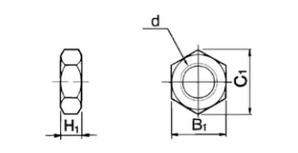
Dimensional drawings: rod-end nut / accessory
(Units: mm)
| Part No. | Applicable Tube Bore Size (mm) |
d | H1 | B1 | C1 |
|---|---|---|---|---|---|
| NT-015A | 20 | M6 × 1.0 | 5 | 10 | 11.5 |
| NT-02 | 25 | M8 × 1.25 | 5 | 13 | 15.0 |
| NT-03 | 32 | M10 × 1.25 | 6 | 17 | 19.6 |
Material: carbon steel
Proper Auto Switch Mounting Position (Detection at Stroke End) and Mounting Height
(Units: mm)
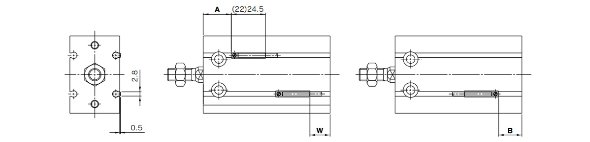
Dimensional drawings: D-A9□/D-M9□/D-M9□W/D-M9□A
*( ): denotes the values of D-A96.
(Units: mm)
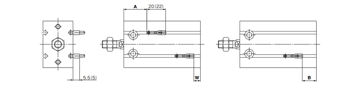
Dimensional drawings: D-A9□V/D-M9□V/D-M9□WV/D-M9□AV
*( ): denotes the values of D-M9□V/D-M9□WV.
(Units: mm)
| Tube inner diameter (mm) |
D-A9□, D-A9□V | D-M9□, D-M9□W | D-M9□V, D-M9□WV | D-M9□A | D-M9□AV | ||||||||||
|---|---|---|---|---|---|---|---|---|---|---|---|---|---|---|---|
| A | B | W | A | B | W | A | B | W | A | B | W | A | B | W | |
| 20 | 18 | 15 | 13 (10.5) | 22 | 19 | 9 | 22 | 19 | 11 | 22 | 19 | 11 | 22 | 19 | 13 |
| 25 | 20 | 11 | 9 (6.5) | 24.5 | 15 | 5 | 24.5 | 15 | 7 | 24.5 | 15 | 7 | 24.5 | 15 | 9 |
| 32 | 22.5 | 13.5 | 11.5 (9) | 26.5 | 17.5 | 7.5 | 26.5 | 17.5 | 9.5 | 26.5 | 17.5 | 9.5 | 26.5 | 17.5 | 11.5 |
- *1Figures in the table above are used as a reference when mounting the auto switches for stroke end detection. When actually setting the auto switches, adjust them after confirming their operation.
- *2Values in ( ) under column W are dimensions for the D-A90 and D-A93 type.
Operating Range
D-A9□, D-A9□V
Bore size 20 mm: 11 mm / Bore size 25 mm: 12.5 mm / Bore size 32 mm: 14 mm
D-M9□, D-M9□V, D-M9□W, D-M9□WV, D-M9□A, D-M9□AV
Bore size 20 mm: 7 mm / Bore size 25 mm: 7 mm / Bore size 32 mm: 7.5 mm
*The operating range is provided as a guideline that includes hysteresis and is not a guaranteed value (assuming approximately ±30% dispersion). It may vary substantially depending on the ambient environment.
Mounting
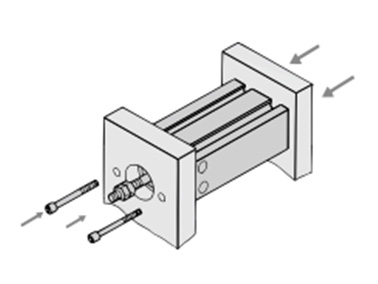
Axial mounting (body tapped)
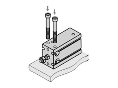
Vertical mounting (body through-holes)
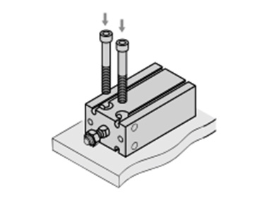
Lateral mounting (body through-holes)
Precautions
Installation and Removal of Retaining Rings
- *Use an appropriate pair of pliers (tool for installing a type C retaining ring) for installation and removal of retaining rings.
- *Even when using an appropriate pair of pliers (tool for installing a type C retaining ring), proceed with caution as there is a danger of the retaining ring flying off the end of the pliers (tool) and causing bodily injury or damage to nearby equipment. After installation, make sure that the retaining ring is securely seated into the retaining ring groove before supplying air.
Selection
- *Operate the cylinder to the stroke end. When the stroke is restricted by an external stopper or a clamped workpiece, sufficient cushioning and noise reduction may not be achieved.
- *Strictly observe the limiting ranges for load weight and maximum speed (Graph 1). Also, the limiting ranges provided here are based on the condition that the cylinder is operated to the stroke end with proper cushion needle adjustment. If operated beyond the limiting ranges, excessive impact will occur and this may cause damage to equipment.
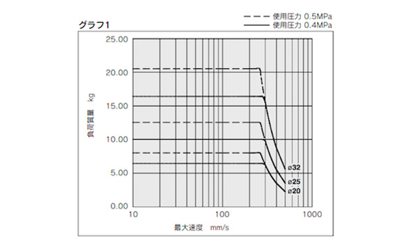
Limiting ranges for load weight and maximum speed (Graph 1)
*See the manufacturer’s catalog for product information other than that detailed above.
Basic Information
| Cylinder Operation Method | Double Acting | Rod Operation Method | Single Rods | Main Body Shape | Plate Cylinder |
|---|---|---|---|---|---|
| Additional Function | Standard | Environment, Applications | Standard | End Locking | No |
| Valves | No | Operating Pressure(MPa) | 0.08::0.7 |
CDU20-20A-A93
CDU20-20A-A93L
CDU20-20A-A93LS
CDU20-20A-A93S
CDU20-20A-A93V
CDU20-20A-A93VLS
CDU20-20A-A96
CDU20-20A-M9B
CDU20-20A-M9BAL
CDU20-20A-M9BAS
CDU20-20A-M9BL
CDU20-20A-M9BS
CDU20-20A-M9BV
CDU20-20A-M9BVLS
CDU20-20A-M9BVS
CDU20-20A-M9BVZ
CDU20-20A-M9BW
CDU20-20A-M9BWL
CDU20-20A-M9BWM
CDU20-20A-M9BWSDPC
CDU20-20A-M9N
CDU20-20A-M9NL
CDU20-20A-M9NS
CDU20-20A-M9NV
CDU20-20A-M9NW
CDU20-30A
CDU20-30A-A93
CDU20-30A-A93L
CDU20-30A-A93LS
CDU25-20A-A90
CDU25-20A-A93L
CDU25-20A-M9BL
CDU25-20A-M9BS
CDU25-20A-M9BVL
CDU25-20A-M9BW
CDU25-20A-M9BWL
CDU25-20A-M9BWV
CDU25-20A-M9NL
CDU25-20A-M9NW
CDU25-30A
CDU25-30A-A93
CDU25-30A-A93L
CDU25-30A-A93LS
CDU25-30A-M9B
CDU25-30A-M9BAL
CDU25-30A-M9BL
CDU25-30A-M9BV
CDU25-30A-M9BVL
CDU25-30A-M9BW
CDU25-30A-M9BWLS
CDU25-30A-M9PL
CDU25-40A
CDU25-40A-A90
CDU25-40A-A93
CDU25-40A-A93L
CDU25-40A-A93LS
CDU25-40A-M9B
CDU25-40A-M9BL
CDU32-20A-A93
CDU32-20A-A93L
CDU32-20A-A93VL
CDU32-20A-A93VLS
CDU32-20A-M9B
CDU32-20A-M9BL
CDU32-20A-M9BW
CDU32-20A-M9BWL
CDU32-20A-M9NWVL
CDU32-30A
CDU32-30A-A93S
CDU32-30A-A93VLS
CDU32-30A-M9BAL
CDU32-30A-M9BL
CDU32-30A-M9BLS
CDU32-30A-M9BV
CDU32-30A-M9BW
CDU32-30A-M9BWL
CDU32-30A-M9BWS
CDU32-30A-M9BWSDPC
CDU32-30A-M9BWVL
CDU32-30A-M9NWL
CDU32-40A
CDU32-40A-A93L
CDU32-40A-A93VL
CDU32-40A-M9B
CDU32-40A-M9BL
CDU32-40A-M9BWL
CDU32-40A-M9N
———————-
👉 Xem thêm sản phẩm của SMC
Liên Hệ Medin Co., Ltd
- Công ty TNHH Mễ Đình được thành lập từ năm 2006.
- Là Đại lý uỷ quyền của SMC tại Việt Nam.
- Từ đó đến nay Medin luôn là Công ty dẫn đầu về lĩnh vực Tự Động Hoá ở thị trường trong và ngoài nước với hơn 1,000 khách hàng, cùng với rất nhiều dự án lớn nhỏ cho các nhà máy sản xuất.
- Chúng tôi cung cấp cho khách hàng những giải phát tuyệt vời nhất trong việc ứng dụng Tự Động Hoá vào sản xuất
- Phương châm: “Giải pháp của chúng tôi, lợi ích của khách hàng”
- Giá trị cốt lõi: “Uy tín là sự tồn tại của chúng tôi”
![]()
- Hơn 20 năm kinh nghiệm, chúng tôi có đội ngũ kỹ sư nhiều kinh nghiệm, có khả năng tư vấn, đưa ra giải pháp có lợi nhất cho khách hàng.
- Sự tin tưởng và đồng hành của khách hàng là động lực để Medin phát triển cao hơn và xa hơn.
👉 Nếu bạn có bất kỳ yêu cầu nào, vui lòng liên hệ với chúng tôi.
☎️ Hotline: 0902782082
![]() 3 Chi nhánh tại HCM, HN, Đà Nẵng
3 Chi nhánh tại HCM, HN, Đà Nẵng
👉 Tham khảo thêm bài viết trên Fanpage
👉 Tham khảo thêm video tại kênh Youtube