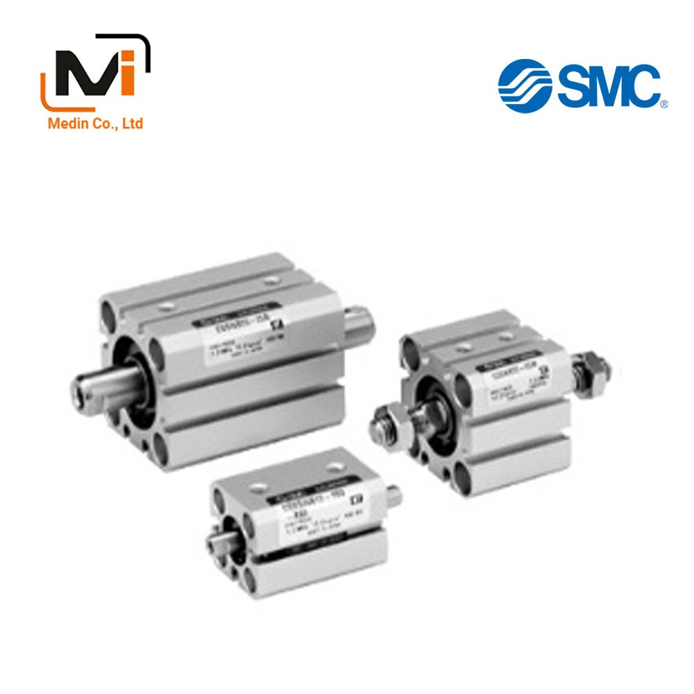
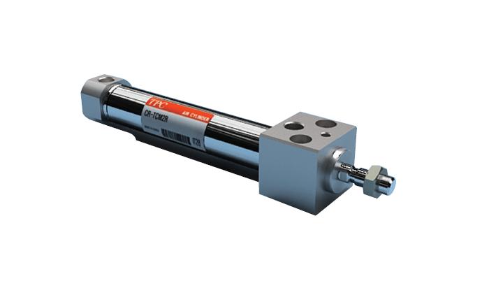
Compact Cylinder, Standard Type, Double Acting, Double Rod CQSW Series – Xi Lanh Khí Nén SMC
Product Description
– Xi Lanh Khí Nén SMC
Compact Cylinder, Standard Type, Double Acting, Double Rod that that is ideal for machine designs with small space requirements.
[Features]
· Square body shape that gives you flexibility for designing machines.
· 2-way basic mounting.
· Non-rotating rod with high non-rotating accuracy.
Danh mục: AUTOMATION, Compact Cylinders - Xi Lanh Khí Nén SMC, SMC
Download
Compact Cylinder, Standard Type, Double Acting, Double Rod CQSW Series Details – Xi Lanh Khí Nén SMC

Compact Cylinder, Standard Type, Double Acting, Double Rod CQSW Series product image
Compact Cylinder, Standard Type, Double Acting, Double Rod CQSW Series Specifications
Model Number Notation
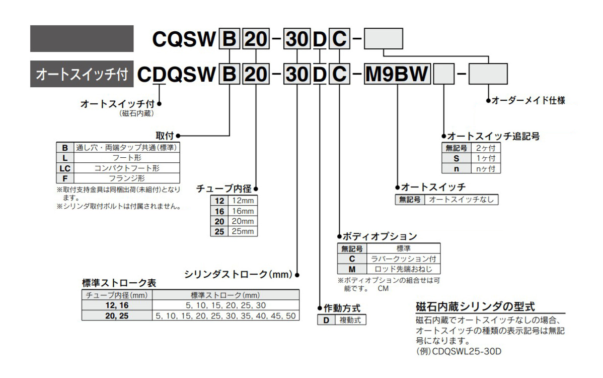
Model number example
Individual Made-to-Order Specifications
| Indicator symbol | Specifications/contents |
|---|---|
| -X235 | Change of piston rod end of double rod cylinder |
| -X271 | Fluororubber seals |
| -X633 | Intermediate stroke of double rod cylinder |
Made to order specifications
| Indicator symbol | Specifications/contents |
|---|---|
| -XA□ | Change of rod-end shape |
| -XB6 | Heat-resistant cylinder (-10 to 150°C) without an auto switch |
| -XB7 | Cold-resistant cylinder (-40 to 70°C) without an auto switch |
| -XB9 | Low speed cylinder (10 to 50 mm/s) |
| -XB10 | Intermediate stroke (using exclusive body) |
| -XB13 | Low speed cylinder (5 to 50 mm/s) |
| -XC6 | Piston rod, retaining ring, rod-end nut made of stainless steel |
| -XC36 | With boss on rod side |
| -XC85 | Grease for food processing equipment |
Standard specification
| Tube Internal Diameter (mm) | 12 | 16 | 20 | 25 | |
|---|---|---|---|---|---|
| Operating method | Double acting, double rod | ||||
| Applicable fluids | Air | ||||
| Lubrication | Not required (non-lube) | ||||
| Proof pressure | 1.5 MPa | ||||
| Maximum operating pressure | 1.0 MPa | ||||
| Minimum operating pressure | 0.07 MPa | 0.05 MPa | |||
| Ambient and working fluid temperature | Without auto switch: -10°C to 70°C (No freezing) | ||||
| With auto switch: -10°C to 60°C (No freezing) | |||||
| Cushioning | None, rubber bumper | ||||
| Rod-end thread | Female thread | ||||
| Stroke length tolerance | +1.0 mm* 0 |
||||
| Operating piston speed | 50 to 500 mm/s | ||||
| Allowable kinetic energy J | Standard type | 0.022 | 0.038 | 0.055 | 0.09 |
| With rubber bumper | 0.043 | 0.075 | 0.11 | 0.18 | |
- *Stroke length tolerance does not include the amount of bumper change.
Structural drawing
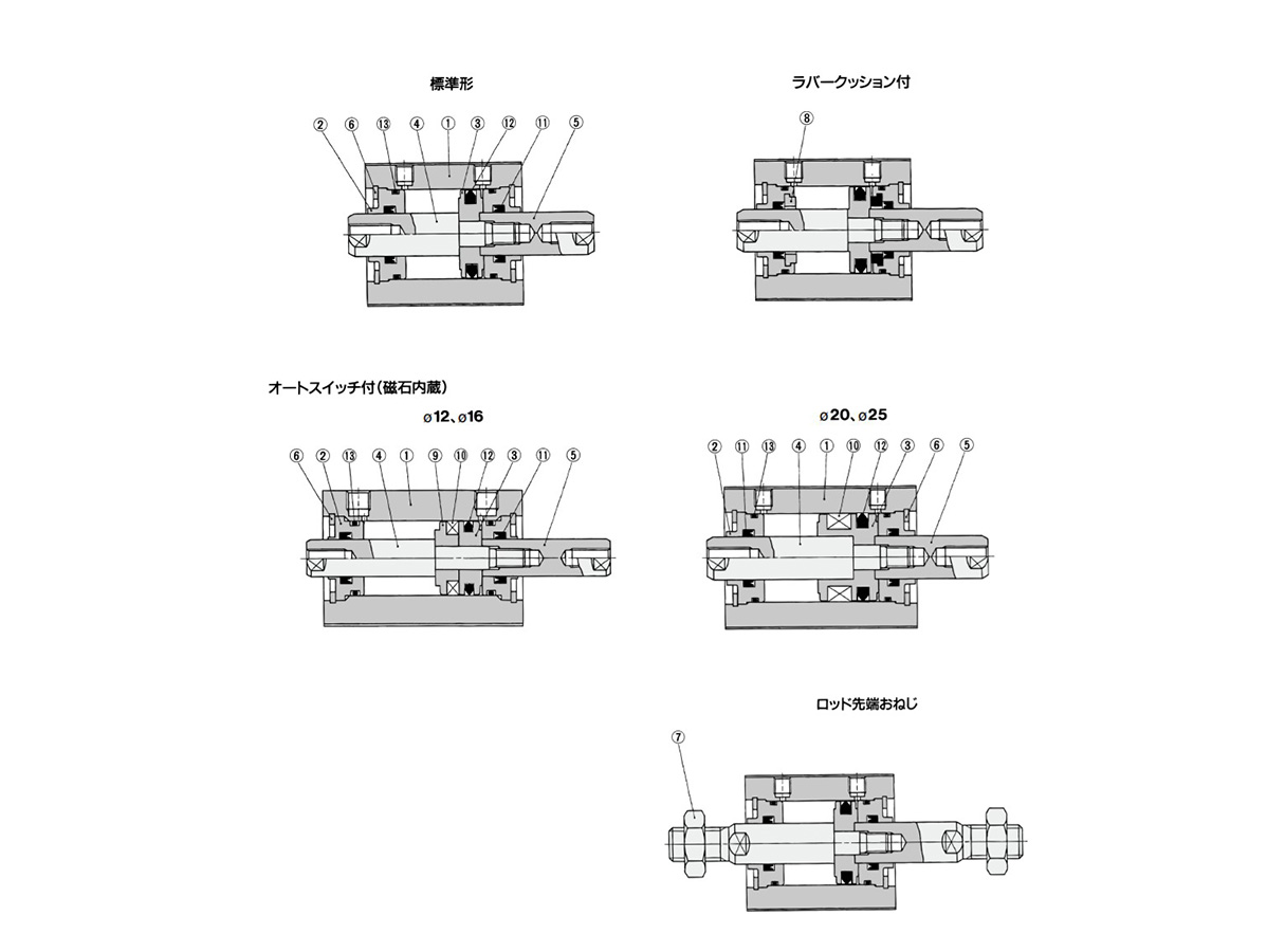
Compact Cylinder, Standard Type, Double Acting, Double Rod CQSW Series Structural Drawing
Component Parts
| Number | Part name | Material | Note |
|---|---|---|---|
| 1 | Cylinder tube | Aluminum Alloy | Hard Anodize |
| 2 | Collar | Aluminum Alloy | Anodized |
| 3 | Piston | Aluminum Alloy | – |
| 4 | Piston rod A | Stainless steel | – |
| 5 | Piston rod B | Stainless steel | – |
| 6 | Retaining Ring | Carbon tool steel | Phosphate coated |
| 7 | Rod-end nut | Carbon steel | Zinc chromate |
| 8 | Dampers | Urethane | – |
| 9 | Spacer for switch | Aluminum Alloy | Chromate |
| 10 | Magnet | – | – |
| 11 | Rod Gasket | NBR | – |
| 12 | Piston Gasket | NBR | – |
| 13 | Tube gasket | NBR | – |
Replacement Parts / Seal Kit
| Tube Internal Diameter (mm) | Order number | Content |
|---|---|---|
| 12 | CQSWB12-PS | A set of (11), (12), (13) listed above |
| 16 | CQSWB16-PS | |
| 20 | CQSWB20-PS | |
| 25 | CQSWB25-PS |
- *Seal kit includes (11), (12) and (13). Order the seal kit based on each bore size.
- *The seal kit does not include a grease pack, so please order a grease pack separately.
Grease pack part number: GR-S-010 (10 g)
Compact Cylinder, Standard Type, Double Acting, Double Rod CQSW Series Example Dimensions
(Unit: mm)
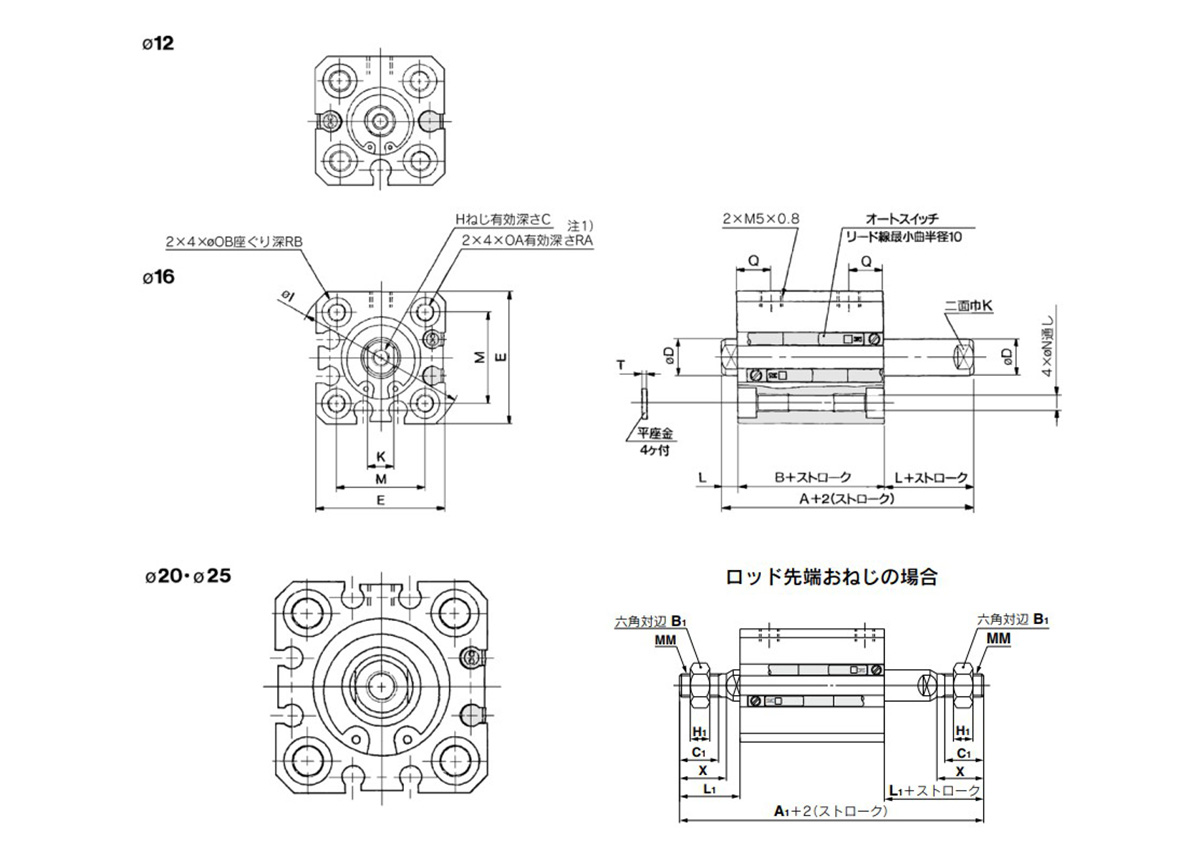
Standard type (through-hole / both ends tapped common): CQSWB/CDQSWB dimensional drawing
Male rod end
(Unit: mm)
| Bore size (mm) |
Without auto switch | With auto switch | B1 | C1 | H1 | L1 | MM | X |
|---|---|---|---|---|---|---|---|---|
| A1 | A1 | |||||||
| 12 | 50 | 55 | 8 | 9 | 4 | 14 | M5 × 0.8 | 10.5 |
| 16 | 53 | 58 | 10 | 10 | 5 | 15.5 | M6 × 1.0 | 12 |
| 20 | 63 | 73 | 13 | 12 | 5 | 18.5 | M8 × 1.25 | 14 |
| 25 | 74 | 84 | 17 | 15 | 6 | 22.5 | M10 × 1.25 | 17.5 |
Standard type
(Unit: mm)
| Bore size (mm) |
Stroke range (mm) |
Without auto switch | With auto switch | C | D | E | H | I | K | L | M | N | OA | OB | Q | RA | RB | T | ||
|---|---|---|---|---|---|---|---|---|---|---|---|---|---|---|---|---|---|---|---|---|
| A | B | A | B | |||||||||||||||||
| 12 | 5 to 30 | 29 | 22 | 34 | 27 | 6 | 6 | 25 | M3 × 0.5 | 32 | 5 | 3.5 | 15.5 | 3.5 | M4 × 0.7 | 6.5 | 7.5 | 7 | 4 | 0.5 |
| 16 | 5 to 30 | 29 | 22 | 34 | 27 | 8 | 8 | 29 | M4 × 0.7 | 38 | 6 | 3.5 | 20 | 3.5 | M4 × 0.7 | 6.5 | 7.5 | 7 | 4 | 0.5 |
| 20 | 5 to 50 | 35 | 26 | 45 | 36 | 7 | 10 | 36 | M5 × 0.8 | 47 | 8 | 4.5 | 25.5 | 5.4 | M6 × 1.0 | 9 | 8 | 10 | 7 | 1 |
| 25 | 5 to 50 | 39 | 29 | 49 | 39 | 12 | 12 | 40 | M6 × 1.0 | 52 | 10 | 5 | 28 | 5.4 | M6 × 1.0 | 9 | 9 | 10 | 7 | 1 |
- *Note 1) For the following bore/stroke sizes, the through-hole is threaded: Standard type: ø20 (20‑mm diameter), ø25 (25‑mm diameter) 5 stroke.
- *Note 2) Rubber bumper type has the same dimensions as those indicated above.
- *Note 3) The positions of the width across flats are not the same on both sides.
Basic Information
| Cylinder Operation Method | Double Acting | Rod Operation Method | Double rod | Main Body Shape | Plate Cylinder |
|---|---|---|---|---|---|
| Additional Function | High rigidity / high precision high class guide |
CDQSWB12-5D
CDQSWB12-5D-A90VS
CDQSWB12-5D-A93VLS
CDQSWB12-5D-A93VS
CDQSWB12-5D-A96VLS
CDQSWB12-5D-M9BV
CDQSWB12-5D-M9BV-X235
CDQSWB12-5D-M9BVL
CDQSWB12-5D-M9BVL-X235
CDQSWB12-5D-A90VS
CDQSWB12-5D-A93VLS
CDQSWB12-5D-A93VS
CDQSWB12-5D-A96VLS
CDQSWB12-5D-M9BV
CDQSWB12-5D-M9BV-X235
CDQSWB12-5D-M9BVL
CDQSWB12-5D-M9BVL-X235
CDQSWB16-5D
CDQSWB16-5D-A90VS
CDQSWB16-5D-A93VLS
CDQSWB16-5D-A93VLS-X235
CDQSWB16-5D-A93VS
CDQSWB16-5D-M9BV
CDQSWB16-5D-M9BVL
CDQSWB16-5D-M9BVL-X235
CDQSWB16-5D-M9BVLS
CDQSWB16-5D-M9BVLS-X235
CDQSWB16-5D-A90VS
CDQSWB16-5D-A93VLS
CDQSWB16-5D-A93VLS-X235
CDQSWB16-5D-A93VS
CDQSWB16-5D-M9BV
CDQSWB16-5D-M9BVL
CDQSWB16-5D-M9BVL-X235
CDQSWB16-5D-M9BVLS
CDQSWB16-5D-M9BVLS-X235
CDQSWB20-5D
CDQSWB20-5D-A90VS
CDQSWB20-5D-A93VLS
CDQSWB20-5D-A93VS
CDQSWB20-5D-M9BV
CDQSWB20-5D-M9BV-XC6
CDQSWB20-5D-M9BVL
CDQSWB20-5D-M9BVLS
CDQSWB20-5D-M9BVLS-X235
CDQSWB20-5D-M9BVS
CDQSWB20-5D-M9BVS-XB9
CDQSWB20-5D-A90VS
CDQSWB20-5D-A93VLS
CDQSWB20-5D-A93VS
CDQSWB20-5D-M9BV
CDQSWB20-5D-M9BV-XC6
CDQSWB20-5D-M9BVL
CDQSWB20-5D-M9BVLS
CDQSWB20-5D-M9BVLS-X235
CDQSWB20-5D-M9BVS
CDQSWB20-5D-M9BVS-XB9
CDQSWB25-5D
CDQSWB25-5D-A93VLS
CDQSWB25-5D-A93VS
CDQSWB25-5D-F8B
CDQSWB25-5D-M9BV
CDQSWB25-5D-M9BV-X271
CDQSWB25-5D-M9BV-XC6
CDQSWB25-5D-M9BVL
CDQSWB25-5D-M9BVL-X271
CDQSWB25-5D-M9BVL-XC6
CDQSWB25-5D-M9BVLS
CDQSWB25-5D-A93VLS
CDQSWB25-5D-A93VS
CDQSWB25-5D-F8B
CDQSWB25-5D-M9BV
CDQSWB25-5D-M9BV-X271
CDQSWB25-5D-M9BV-XC6
CDQSWB25-5D-M9BVL
CDQSWB25-5D-M9BVL-X271
CDQSWB25-5D-M9BVL-XC6
CDQSWB25-5D-M9BVLS
CDQSWB12-5D-A90VS
CDQSWB16-5D-A90VS
CDQSWB20-5D-A90VS
CDQSWB25-5D-A93VS
