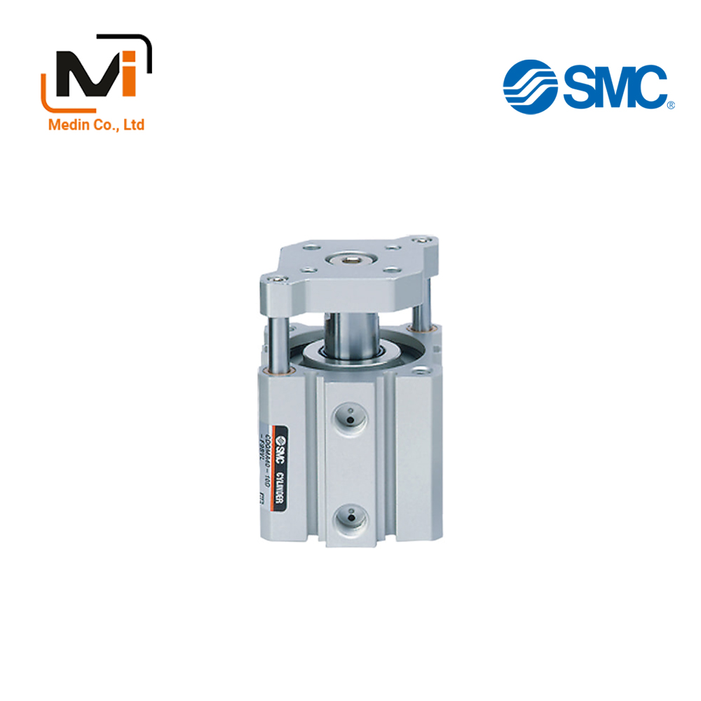
Compact Cylinder, Guide-Rod Type CQM Series – Xi Lanh Khí Nén SMC
Product Description
Compact Cylinder, Guide Rod Type CQM Series to which a load can be directly mounted.
[Features]
· Mounting dimensions compatible with CQS and CQ2 series.
· Auto switch can be mounted/removed even when the plate is retracted.
Download
Compact Cylinder, Guide-Rod Type CQM Series Specifications – Xi Lanh Khí Nén SMC
Model Number Notation
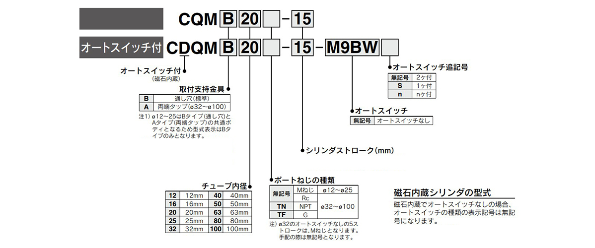
Model Number Notation
Specifications
| Tube Internal Diameter (mm) | 12 | 16 | 20 | 25 | 32 | 40 | 50 | 63 | 80 | 100 |
|---|---|---|---|---|---|---|---|---|---|---|
| Model | Pneumatic (non-lube) type | |||||||||
| Operating method | Double acting, single rod | |||||||||
| Applicable fluids | Air | |||||||||
| Proof pressure | 1.5 MPa | |||||||||
| Maximum operating pressure | 1.0 MPa | |||||||||
| Minimum operating pressure | 0.12 MPa | 0.1 MPa | ||||||||
| Ambient and working fluid temperature | Without auto switch: -10°C to +70°C (No freezing) With auto switch: -10°C to +60°C (No freezing) |
|||||||||
| Cushioning | Rubber bumper at both ends | |||||||||
| Stroke length tolerance | +1.0 mm* 0 |
|||||||||
| Mounting | Through hole | |||||||||
| Operating piston speed | 50 to 500 mm/s | 50 to 300 mm/s | ||||||||
- *Stroke length tolerance does not include the amount of bumper change.
Standard stroke
| Tube Internal Diameter (mm) | Standard stroke (mm) |
|---|---|
| 12, 16 | 5, 10, 15, 20, 25, 30 |
| 20, 25 | 5, 10, 15, 20, 25, 30, 35, 40, 45, 50 |
| 32, 40 | 5, 10, 15, 20, 25, 30, 35, 40, 45, 50, 75, 100 |
| 50, 63, 80, 100 | 10, 15, 20, 25, 30, 35, 40, 45, 50, 75, 100 |
Structural drawing
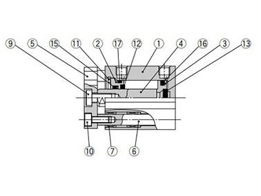
ø12 to ø25 (12‑ to 25‑mm bore size)
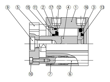
ø32 to ø100 (32‑mm to 100‑mm bore size)
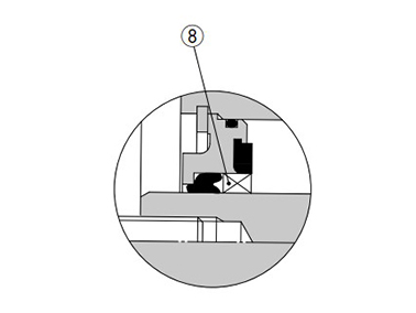
ø50 to ø100 (50‑mm to 100‑mm bore size)
Component Parts
| Number | Description | Material | Note |
|---|---|---|---|
| 1 | Cylinder tube | Aluminum Alloy | Hard Anodize |
| 2 | Collar | Aluminum Alloy | ø12 to ø40 (12‑mm to 40‑mm bore size) Anodized |
| Aluminum alloy casting | ø50 to ø100 (50‑mm to 100‑mm bore size) Chromate, coated | ||
| 3 | Piston | Aluminum Alloy | – |
| 4 | Piston rod | Stainless steel | ø12 to ø25 (12‑mm to 25‑mm bore size) |
| Carbon steel | ø32 to ø100 (32‑mm to 100‑mm bore size) Hard chrome plated | ||
| 5 | Plate | Aluminum Alloy | Anodized |
| 6 | Guide rod | Stainless steel | – |
| 7 | Bushing | Resin/Copper alloy (Multiple layers) | – |
| 8 | Bushing | Resin/Copper alloy (Multiple layers) | ø50 to ø100 (50‑mm to 100‑mm bore size) |
| 9 | Hexagon socket head bolt | Carbon steel | Zinc chromate |
| 10 | Hexagon socket head bolt | Carbon steel | Zinc chromate |
| 11 | Retaining Ring | Carbon tool steel | Phosphate coated |
| 12 | Bumper A | Urethane | – |
| 13 | Damper B | Urethane | – |
| 14 | Magnet | – | – |
| 15 | Rod Gasket | NBR | – |
| 16 | Piston Gasket | NBR | – |
| 17 | Gasket | NBR | – |
Compact Cylinder, Guide-Rod Type CQM Series Example Dimensions
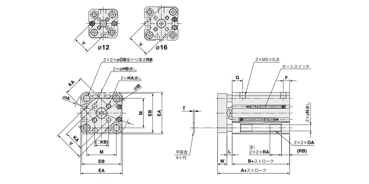
ø12 to ø25 (12‑ to 25‑mm bore size) dimensional drawing
(Unit: mm)
| Bore size (mm) |
Stroke range (mm) |
Without auto switch | With auto switch | EA | EB | F | HA | OA | HB | IA | IB | ||
|---|---|---|---|---|---|---|---|---|---|---|---|---|---|
| A | B | A | B | ||||||||||
| 12 | 5 to 30 | 26.5 | 17 | 31.5 | 22 | 25 | 24 | 5 | M3 × 0.5 | M4 × 0.7 | 3 (0 to +0.2) | 32 | 31.5 |
| 16 | 5 to 30 | 26.5 | 17 | 31.5 | 22 | 29 | 28 | 5 | M3 × 0.5 | M4 × 0.7 | 3 (0 to +0.2) | 38 | 37 |
| 20 | 5 to 50 | 32 | 19.5 | 42 | 29.5 | 36 | 34 | 5.5 | M4 × 0.7 | M6 × 1.0 | 4 (0 to +0.2) | 47 | 45.5 |
| 25 | 5 to 50 | 35.5 | 22.5 | 45.5 | 32.5 | 40 | 38 | 5.5 | M5 × 0.8 | M6 × 1.0 | 5 (0 to +0.2) | 52 | 50.5 |
(Unit: mm)
| Bore size (mm) |
KA | KB | L | M | N | OB | Q | RA | RB | T | V | W |
|---|---|---|---|---|---|---|---|---|---|---|---|---|
| 12 | 10 ± 0.1 | 7.1 | 3.5 | 15.5 | 3.5 | 6.5 | 7.5 | 7 | 4 | 0.5 | 14.9 | 6 |
| 16 | 14 ± 0.1 | 9.9 | 3.5 | 20 | 3.5 | 6.5 | 7.5 | 7 | 4 | 0.5 | 20 | 6 |
| 20 | 17 ± 0.1 | 12 | 4.5 | 25.5 | 5.4 | 9 | 9 | 10 | 7 | 1 | 26 | 8 |
| 25 | 22 ± 0.1 | 15.6 | 5 | 28 | 5.4 | 9 | 11 | 10 | 7 | 1 | 30 | 8 |
Note) For the following bore/stroke sizes, the through-hole is threaded: Standard without auto switch: ø12 (12‑mm bore size) and ø16 (16‑mm bore size) 5 stroke; ø20 (20‑mm bore size) 5 to 15 stroke; ø25 (25‑mm bore size) 5 and 10 stroke. Built-in magnet with auto switch: ø20 (20‑mm bore size) 5 stroke.
Basic Information
| Cylinder Operation Method | Double Acting | Rod Operation Method | Single Rods | Main Body Shape | Plate Cylinder |
|---|---|---|---|---|---|
| Additional Function | Standard | Environment, Applications | Standard | Cushion | Rubber bumper at both ends |
CDQMB12-2
CDQMB12-3
CDQMB12-4
CDQMB12-5
CDQMB12-5-A90VS
CDQMB12-5-A93VLS
CDQMB12-5-A93VS
CDQMB12-5-A96VLS
CDQMB12-5-M9BV
CDQMB16-1
CDQMB16-2
CDQMB16-3
CDQMB16-4
CDQMB16-5
CDQMB16-5-A93VLS
CDQMB16-5-A93VS
CDQMB16-5-M9BV
CDQMB16-5-M9BV3
CDQMB20-1
CDQMB20-2
CDQMB20-3
CDQMB20-4
CDQMB20-5
CDQMB20-5-A93VLS
CDQMB20-5-A93VS
CDQMB20-5-A96VS
CDQMB25-2
CDQMB25-3
CDQMB25-4
CDQMB25-5
CDQMB25-5-A90VLS
CDQMB25-5-A93M
CDQMB25-5-A93VLS
CDQMA32-1
CDQMA32-2
CDQMA32-3
CDQMA32-4
CDQMA32-5
CDQMA32-5-A93VLS
CDQMA32-5-A93VS
CDQMA32-5-A93VZS
CDQMA40-5
CDQMA40-5-A93VLS
CDQMA40-5-M9BV
CDQMA40-5-M9BVL
CDQMA40-5-M9BVLS
CDQMA40-5-M9BVS
CDQMA40-5-M9BVZ
CDQMA40-5-M9NV
CDQMA40-5-M9NVL
CDQMA50-5-M9PV
CDQMA50-10
CDQMA50-10-A73L
CDQMA50-10-A93
CDQMA50-10-A93L
CDQMA63-5
CDQMA63-10
CDQMA63-10-A73Z
CDQMA63-10-A93
CDQMA63-10-A93L
CDQMA63-10-A93VL
CDQMA63-10-A93Z
CDQMA80-10
CDQMA80-10-A93
CDQMA80-10-A93V
CDQMA80-10-A93VL
CDQMA80-10-A93VS
CDQMA80-10-M9B
CDQMA80-10-M9BL
CDQMA100-10
CDQMA100-10-A93VS
CDQMA100-10-A93Z
CDQMA100-10-M9B
CDQMA100-10-M9BVL
CDQMA100-10-M9BVZS
CDQMA100-10-M9BWVS
CDQMA100-10-M9NVL
CDQMB12-5-A90VS
CDQMB16-5-A93VLS
CDQMB20-5-A93VLS
CDQMB25-5-A90VLS
CDQMA32-5-A93VLS
CDQMA40-5-A93VLS
CDQMA50-10-A73L
CDQMA63-10-A73Z
CDQMA80-10-A93VL
CDQMA100-10-A93VS
