Bộ lọc khí SMC Air Filter LLB Series LLB3 LLB4 LVB2 LVB3 LVB4
Clean Air Module (Standard / High Flow Type), LLB Series
Modularized (reduces piping labor hours / saves space) to allow clean air to be obtained easily.
Download

Bộ lọc khí SMC Air Filter LLB Series LLB3 LLB4 LVB2 LVB3 LVB4
Clean Air Module, LLB Series Specifications – Bộ lọc khí SMC
[Features] · Filtration: 0.01 μm (filtration efficiency 99.99%).· Fluid contact space: Grease-free, silicone-free.
· Available in 24 variations of combinations.
· Built-in single-action fittings.
· Can be fitted with pressure gauge / pressure switch (separate purchase).
· RoHS compliant.
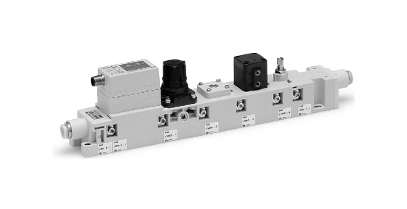
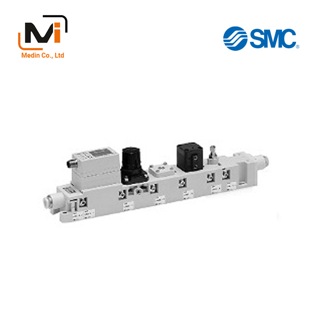
LLB3 external appearance
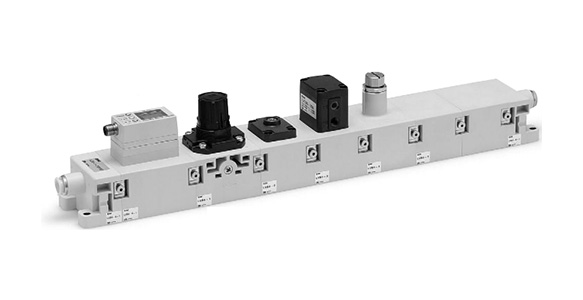
LLB4 external appearance
Clean Air Module Common Specifications
| Model | LLB3 | LLB4 | ||
|---|---|---|---|---|
| Applicable Fluid | Clean Air, N2gas (Inlet air conditions equivalent to ISO 8573-1 and quality class 1.4.1 to 1.6.1)*3 | |||
| Maximum Operating Pressure | 0.7 MPa | |||
| Set Pressure | 0.05 to 0.4 MPa | |||
| Withstand Pressure | 1.0 MPa | |||
| Working Fluid Temperature | 5℃ to 45°C (no freezing) *Guaranteed range of digital flow switch: 15 to 35°C. |
|||
| Ambient Temperature | ||||
| Flow Rate Range*1 | 5 to 100 L/min (ANR) | 50 to 500 L/min (ANR) | ||
| Filtration*2 | 0.01 μm (filtration efficiency 99.99%) | |||
| Fluid Contact Space | – | Grease-free, silicone-free | ||
| Material | Body | PBT | ||
| Module Connection Packing | FKM | |||
| Single-Action Fitting Packing | EPDM | |||
*1: The maximum flow rate varies depending on set pressure. Refer to “Flow Rate Characteristics” graph for details.
*2: Measured under manufacturer’s specified conditions.
*3: Refer to Operating Environment (catalog p. 344).
Digital Flow Switch Unit Specifications
| Model | LLB3 | LLB4 | ||
|---|---|---|---|---|
| Detection Type | Heat type | |||
| Measured Flow Rate Range | 5 to 100 L/min | 50 to 500 L/min | ||
| Minimum Unit Setting | 1 L/min | 5 L/min | ||
| Accumulated Pulse Flow Rate Exchange Value (Pulse Width: 50 [ms]) | 1 L/pulse | 5 L/pulse | ||
| Accumulated Flow Rate Range | 0 to 999,999 L | |||
| Linearity | ±5% F.S. or less (15 to 35°C, 25°C reference) | |||
| Repeatability | ±2% F.S. or less | |||
| Temperature Characteristics | ±5% F.S. or less (15 to 35°C, 25°C reference) | |||
| Specifications | Switch Output | – | NPN or PNP open collector output | |
| Maximum Load Current | 80 mA | |||
| Maximum Applied Voltage | 30 V DC (at NPN output) | |||
| Internal Voltage Drop | NPN output: 1 V or less (at 80 mA) PNP output: 1.5 V or less (at 80 mA) | |||
| Analog Output | Voltage Output | Output voltage 1 to 5 V | ||
| Allowable load resistance 100 kΩ or more | ||||
| Current Output | Output current 4 to 20 mA | |||
| Allowable load resistance 300Ω or less (12 V DC), 600Ω or less (24 V DC) | ||||
| Status LEDs | When turned ON, OUT1: Green, OUT2: Red (where output is analog, OUT1 only) | |||
| Response Time | 1S or less | |||
| Power Supply Voltage | 12 to 24 V DC (Ripple ±10% or less) | |||
| Current Consumption | 160 mA or less | 170 mA or less | ||
| Withstand Voltage | 1,000 V AC, for 1 minute between external terminal and case | |||
| Insulation Resistance | 50 MΩ or more (500 V DC measured with megohmmeter) between external terminal and case | |||
| Noise Resistance | 1,000 V p-p, pulse width 1 μs, rise time 1 ns | |||
| Lead Wire | Lead wire with connector | |||
| Enclosure | IP65 | |||
| Fluid Contact Space Material | Mesh | SUS | ||
| Sensor Housing | PBT | |||
| Sensor | Lead glass (RoHS-exempt material) | |||
| Ptlr | ||||
| FeNl | ||||
ON/OFF Valve Unit Specifications
| Model | LLB3 | LLB4 | |
|---|---|---|---|
| Pilot Pressure (ON/OFF Valve Operating Pressure) | 0.4 to 0.5 MPa | ||
| Back Pressure | 0.4 MPa or less | ||
| Valve Type | N.C. | ||
| Orifice Diameter | 4 mm | 8 mm | |
| Cv Factor | 0.35 | 1.7 | |
| Fluid Contact Space Material | Diaphragm | PTFE | |
| Valve Leakage | 1 cm3/min (ANR) or less | ||
Filter Unit Specifications
| Model | LLB3 | LLB4 | |
|---|---|---|---|
| Filtration*1 | 0.01 μm (filtration efficiency 99.99%) | ||
| Element Proof Differential Pressure*2 | 0.5 MPa | ||
| Processing Flow Rate | Up to 100 L/min (ANR) | Up to 500 L/min (ANR) | |
| Fluid Contact Space Material | Filter Case | PC | |
| Hollow Fiber | PP | ||
| Potting | PU | ||
*1: Measured under manufacturer’s specified conditions.
*2: This means that the element will not break at 0.5 MPa. Refer to installation precautions prior to use.
Pressure Reducing Valve Unit Specifications
- Relief mechanism: LLB3, LLB4 / Non-relief
- Fluid contact space material (Diaphragm): LLB3, LLB4 / FKM
Throttle Valve Unit Specifications
- Cv factor: LLB3 / 0.28, LLB4 / 1.4
- Number of needle rotations: LLB3 / 8 rotations, LLB4 / 10 rotations
- Fluid contact space material (needle): LLB3, LLB4 / SUS
Product Outline Dimensional Drawing
(Unit: mm)
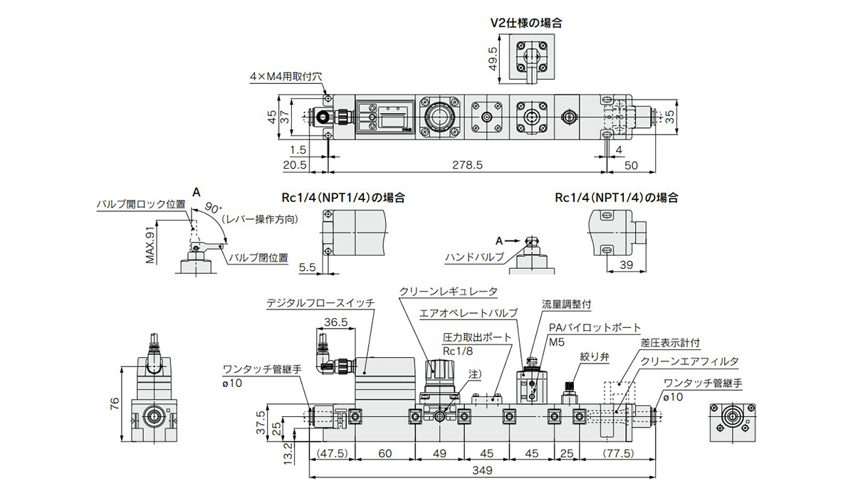
LLB3-1-P□R□V□SF dimensional drawing
*Cannot be used. If a pressure gauge, etc. is screwed in, there is risk of damage.
(Unit: mm)
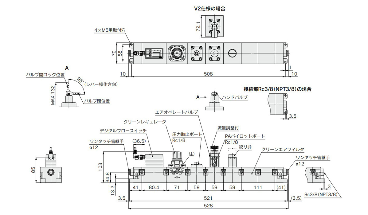
LLB4-1-P□R□V□SF dimensional drawing
*Cannot be used. If a pressure gauge, etc. is screwed in, there is risk of damage.
Component Parts
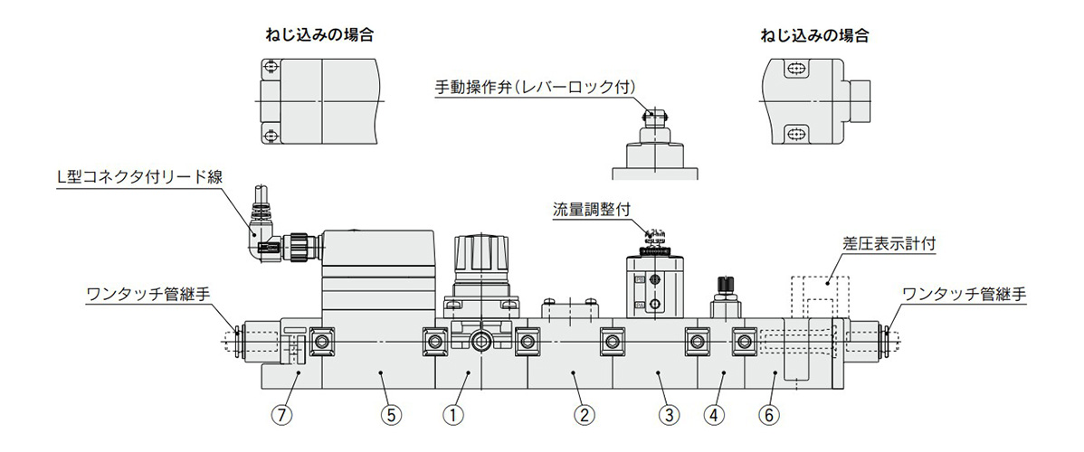
LLB Series component parts
| No. | Description | Note | |
|---|---|---|---|
| 1 | Clean regulator ass’y | – | – |
| 2 | Pressure outlet port ass’y | – | – |
| 3 | ON/OFF valve ass’y / Air operated valve | Without flow adjuster | – |
| With flow adjuster | – | ||
| ON/OFF valve ass’y / Manual operation valve | – | – | |
| 4 | Throttle valve ass’y | – | – |
| 5 | Digital flow switch ass’y | 5 to 100 L/min | With L-type connector With lead wire (3 m) |
| 50 to 500 L/min | |||
| 6 | Clean air filter ass’y | øWith 10-mm diameter fitting | With single-action fitting |
| Rc 1/4 | Threaded type | ||
| NPT 1/4 | |||
| øWith 10-mm diameter pipe fitting, with differential pressure gauge | With single-action fitting | ||
| Rc 1/4, with differential pressure gauge | Threaded type | ||
| NPT 1/4, with differential pressure gauge | |||
| Replacement element | – | ||
| 7 | End plate ass’y | øWith 10-mm diameter fitting | With single-action fitting |
| Rc 1/4 | Threaded type | ||
| NPT 1/4 | |||
| øWith 12-mm diameter fitting | With single-action fitting | ||
| Rc 3/8 | Threaded type | ||
| NPT 3/8 | |||
*Each module comes with 2 connection fittings.
Product Flow Rate Characteristics
Standard type (100 L/min)
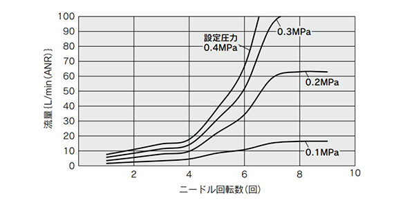
LLB3-1-P1R1VSF flow rate characteristics graph (number of needle rotations)
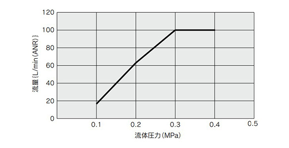
LLB3-1-P1R1VSF flow rate characteristics graph (fluid pressure)
High Flow Type (500 L/min)
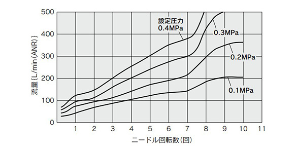
LLB4-1-P1R1VSF flow rate characteristics graph (number of needle rotations)
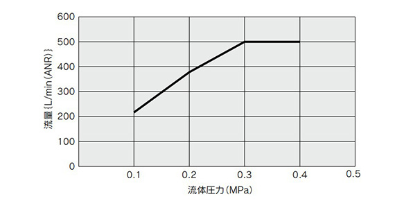
LLB4-1-P1R1VSF flow rate characteristics graph (fluid pressure)
Test Conditions
Product models: LLB3-1-P1R1VSF and LLB4-1-P1R1VSF
Supplied pressure: 0.5 MPa
Pressure setting conditions and measured position: Pressure is set by turning the regulator knob with ON/OFF valve turned off.
Pressure is measured at the pressure outlet port.
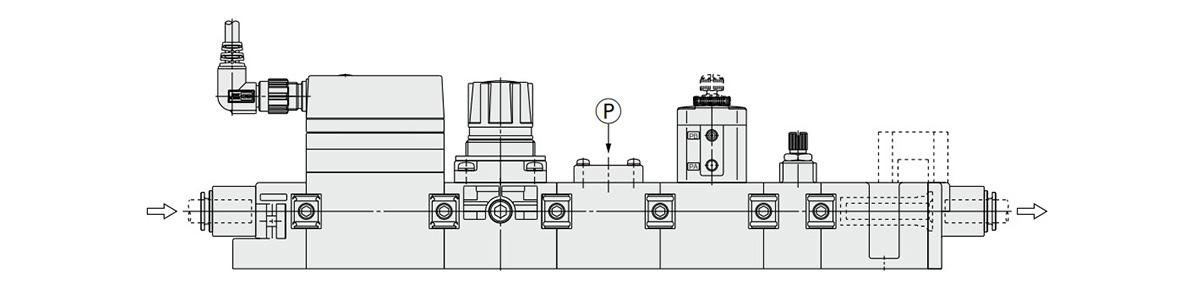
Installation diagram based on test conditions
Precautions
- *Ensure that you read the specific product precautions prior to use.
- *See the manufacturer’s catalog for product information other than the above.
- *Product pictures are example representations for the product series. Please be aware that actual product specifications may be different.
Design and Selection
- *Confirm the specifications: Give due consideration to the operating conditions such as the application, fluid and environment, and use within the operating ranges specified in the manufacturer’s catalog.
- *Ensure sufficient maintenance space: Provide the required space for maintenance inspection.
- *Fluid pressure range: Supplied fluid pressure must be within the operating pressure range specified in the manufacturer’s catalog.
Mounting
- *If air leakage increases, or equipment does not operate correctly, stop use immediately.
- *After mounting, perform suitable function and leak testing to confirm that the mounting is correct.
Basic Information
| Compressed Air Quality | General Dry Air |
|---|
LLB3-1-P1F
LLB3-1-P1F1
LLB3-1-P1R1F
LLB3-1-P1R1F1
LLB3-1-P1R1SF
LLB3-1-P1R1V1F
LLB3-1-P1R1V1SF
LLB3-1-P1R1V1SF1
LLB3-2-F
LLB3-2-F1
LLB3-2-P1R1F
LLB3-2-P1R1SF
LLB3-2-P1R1V1F
LLB3-2-P1R1V1F1
LLB3-2-P1R1V1SF
LLB3-2N-P1R1V1SF1
LLB3-2N-P1RVF
LLB3-2N-P3R1VSF
LLB3-2N-P6VSF
LLB3-2N-R1SF1
LLB3-2N-R1VSF
LLB4-1-P1F
LLB4-1-P1R1F
LLB4-1-P1R1SF
LLB4-1-P1R1V1F
LLB4-1-P1R1V1SF
LLB4-1-P1R1V2F
LLB4-1-P1R1V2SF
LLB4-3-F
LLB4-3-P1F
LLB4-3-P1R1F
LLB4-3-P1R1SF
LLB4-3-P1R1V1F
LLB4-3-P1R1V1SF
LLB4-3-P1R1V2F
LLB4-3-P1R1V2SF
LLB4-3N-P1RVF
LLB4-3N-P1RVSF
LLB4-3N-R1F
LVB2-3-1
LVB2-3-2
LVB2-4
LVB3-1
LVB3-2
LVB3-6-1
LVB3-6-2
LVB3-6-3
LVB3-6-4
LVB3-6-5
LVB3-6-6
LVB3-7-2
LVB3-7-2-1
LVB3-7-3
LVB3-7-3-1
LVB4-1
LVB4-2
LVB4-3
LVB4-3-1
LVB4-3-2
LVB4-4
LVB4-6-1
Giới thiệu SMC Việt Nam
SMC là thương hiệu hàng đầu thế giới trong lĩnh vực công nghệ khí nén, cung cấp các giải pháp tiên tiến nhằm hỗ trợ tự động hóa và tối ưu hóa quy trình sản xuất.
Với nền tảng vững chắc trong ngành, SMC Việt Nam luôn đi đầu trong việc nghiên cứu, đổi mới và phát triển sản phẩm, góp phần nâng cao năng suất và tiết kiệm lao động cho các doanh nghiệp công nghiệp.
Với phương châm “đóng góp vào tự động hóa và tiết kiệm lao động trong ngành công nghiệp”, SMC Việt Nam không ngừng cải tiến và mang đến những sản phẩm công nghệ tiên tiến nhất.
SMC Việt Nam cam kết cung cấp những giải pháp hiện đại, giúp khách hàng duy trì lợi thế cạnh tranh trên thị trường.
Medin Company cung cấp các sản phẩm SMC tại Việt Nam.
Đa dạng các sản phẩm và giải pháp khí nén phục vụ cho nhiều ngành công nghiệp khác nhau, bao gồm:
- Xy lanh khí nén – Giúp kiểm soát chuyển động chính xác và hiệu quả.
- Van điện từ – Ứng dụng rộng rãi trong điều khiển luồng khí nén.
- Bộ lọc khí nén – Đảm bảo chất lượng khí nén tối ưu.
- Cảm biến và bộ điều khiển – Tăng cường tự động hóa trong quy trình sản xuất.
———————-
👉 Xem thêm sản phẩm của SMC
Liên Hệ Medin Co., Ltd
- Công ty TNHH Mễ Đình được thành lập từ năm 2006.
- Từ đó đến nay Medin luôn là Công ty dẫn đầu về lĩnh vực Tự Động Hoá ở thị trường trong và ngoài nước với hơn 1,000 khách hàng, cùng với rất nhiều dự án lớn nhỏ cho các nhà máy sản xuất.
- Chúng tôi cung cấp cho khách hàng những giải phát tuyệt vời nhất trong việc ứng dụng Tự Động Hoá vào sản xuất
- Phương châm: “Giải pháp của chúng tôi, lợi ích của khách hàng”
- Giá trị cốt lõi: “Uy tín là sự tồn tại của chúng tôi”
![]()
- Hơn 20 năm kinh nghiệm, chúng tôi có đội ngũ kỹ sư nhiều kinh nghiệm, có khả năng tư vấn, đưa ra giải pháp có lợi nhất cho khách hàng.
- Sự tin tưởng và đồng hành của khách hàng là động lực để Medin phát triển cao hơn và xa hơn.