Xi Lanh Kẹp SMC MA3 Series MA310 MA311 MA320 MA321 MHR2 MHZ2
Auto Hand Changing System (AHC), MA3 Series
The AHC system changes robot hand tools automatically to accommodate workpieces of different shapes, thus making it possible to adopt FMS on the assembly line.
Download
Xi Lanh Kẹp SMC MA3 Series MA310 MA311 MA320 MA321 MHR2 MHZ2
AHC System MA3 Series Features – Xi Lanh Kẹp SMC
[Features] · No adjustment or teaching required when changing tools.· Accelerated launch of assembly lines.

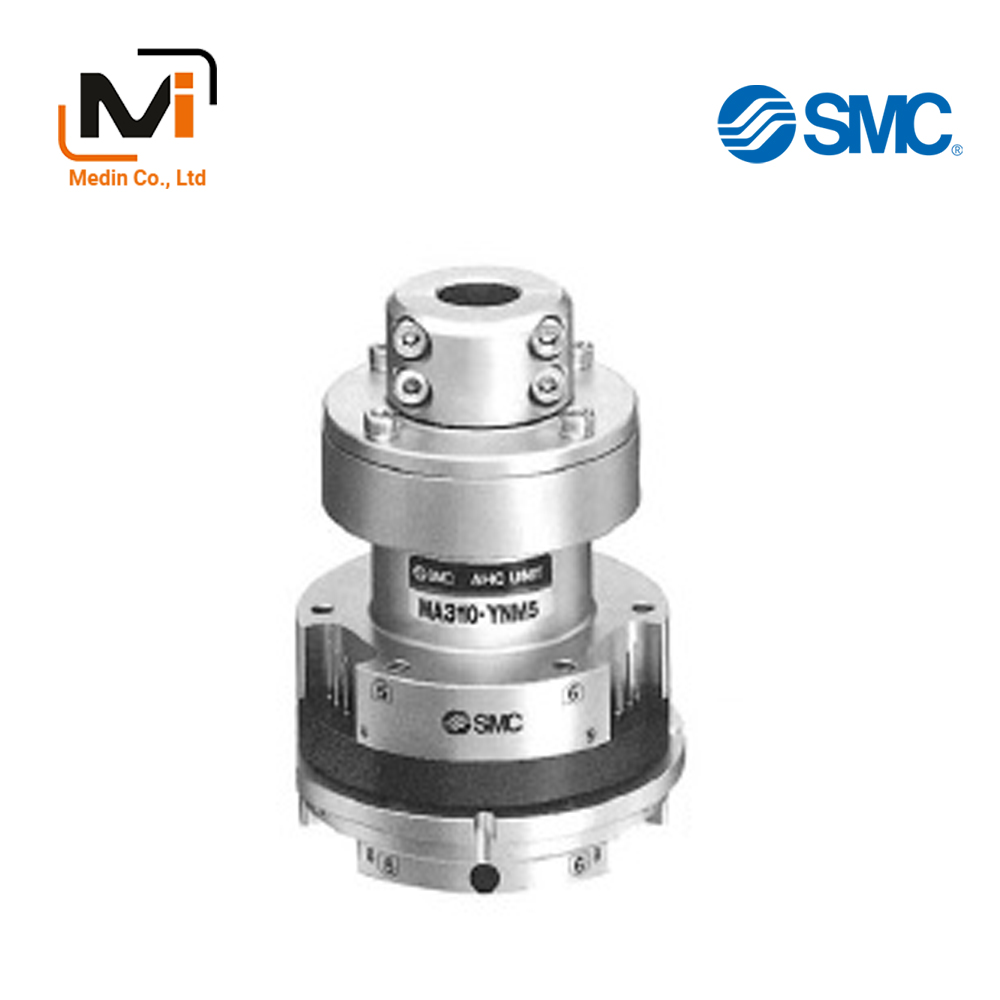
AHC System MA3 Series external appearance
Specifications
| Series | MA310 | MA311 | MA320 | MA321 | ||
|---|---|---|---|---|---|---|
| Positioning | Ball coupling | Curvic coupling | ||||
| Max. transportable weight | 5 kg | |||||
| Handling | Single acting / air supply at separation | Double acting | Single acting / air supply at separation | Double acting | ||
| Handling air pressure | 0.4 to 0.7 MPa | |||||
| Proof pressure | 1.05 MPa | |||||
| Ambient and fluid temperature | 0 to 60°C | |||||
| Positioning repeatability | ±0.01 mm | |||||
| Combined axial force W* | 200 N | 500 N (at 0.5 MPa) |
200 N | 500 N (at 0.5 MPa) |
||
| Moment resistance M* | 3 N·m | 7.5 N·m (at 0.5 MPa) |
3 N·m | 7.5 N·m (at 0.5 MPa) |
||
| Torque resistance T* | 3 N·m | 7.5 N·m (at 0.5 MPa) |
12 N·m | 30 N·m (at 0.5 MPa) |
||
| Interface | Air | Max. operating pressure | 0.7 MPa | |||
| Operating vacuum pressure | -100 kPa or more (10 Torr or more) | |||||
| Cv value | 0.072 | |||||
| Number of circuits | 6 | |||||
| Electricity | Contact point capacity | 2 A / interface | ||||
| Number of contact points | 12 | |||||
- *Values given in the table for combined axial force, moment resistance, and torque resistance are the values for when the AHC unit and the tool adapter begin to separate.
For safety reasons, make sure that the axial force, moment, and torque from the load are 1/2 or less than the values above during use.
Option Part No.
Robot Adapter
| Part no. | Applicable shaft diameter | Note |
|---|---|---|
| MA310-CR1 | ø10 (applicable shaft diameter 10 mm) | Hex socket head cap screw M4 × 10 (4) M4 × 14 (4 pcs.) |
| MA310-CR2 | ø11 (applicable shaft diameter 11 mm) | |
| MA310-CR3 | ø14 (applicable shaft diameter 14 mm) | |
| MA310-CR4 | ø15 (applicable shaft diameter 15 mm) | |
| MA310-CR5 | ø20 (applicable shaft diameter 20 mm) | |
| MA310-CS6 | ø24 (applicable shaft diameter 24 mm) | |
| MA310-CR6 | ø25 (applicable shaft diameter 25 mm) |
Additional Installation Unit of Electrical Contacts
| Part no. | Additional installation unit | Application | Note |
|---|---|---|---|
| MA310-EY1 | 8 contact points | For AHC unit | Hex socket head cap screw M2.5 × 10 (2 pcs.) |
| MA310-EA1 | For tool adapter |
Drawing / Components Parts
Single Acting Type
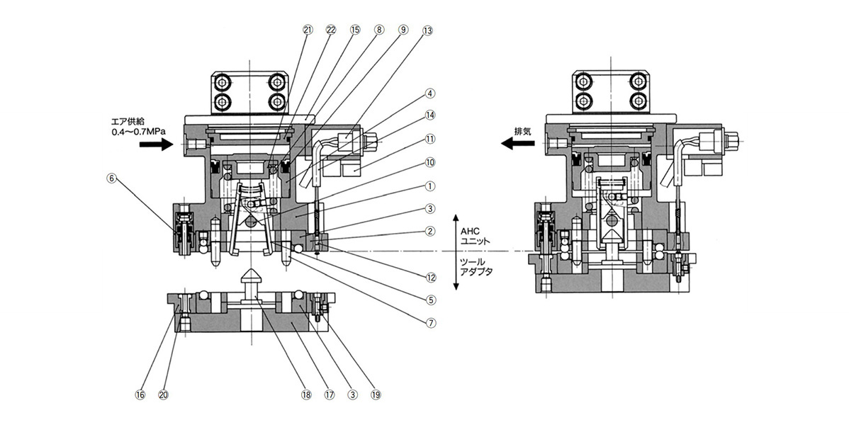
Single acting type structure drawing / component parts
Double Acting Type
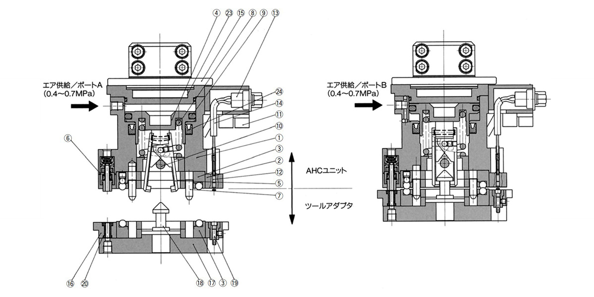
Double acting type structure drawing / component parts
Component Parts
| No. | Description | Material | Note |
|---|---|---|---|
| 1 | Body | Aluminum alloy | Hard anodized |
| 2 | Insulation ring | Synthetic resin | Black |
| 3 | Coupling | Carbon steel | Special black thin-membrane anti-corrosive treated |
| 4 | Piston | Aluminum alloy | Chromate treatment |
| 5 | Lever | Carbon steel | Special black thin-membrane anti-corrosive treated |
| 6 | Check valve ass’y | Brass, steel wire, synthetic rubber | – |
| 7 | Pilot pin | Carbon steel | Special black thin-membrane anti-corrosive treated |
| 8 | Clamp spring | Steel wire | Zinc chromated |
| 9 | Seal | Synthetic rubber | – |
| 10 | Parallel pin | Stainless steel | – |
| 11 | Multi-tube holder | Synthetic resin | Black |
| 12 | Contact probe | – | – |
| 13 | D-sub connector ass’y | – | – |
| 14 | Cable | – | – |
| 15 | Robot Adapter | Aluminum alloy | Hard anodized |
| 16 | Connecting base | Aluminum alloy | Hard anodized |
| 17 | Tool plate | Aluminum alloy | Hard anodized |
| 18 | Hook | Carbon steel | Special black thin-membrane anti-corrosive treated |
| 19 | Contact block ass’y | Beryllium copper, synthetic resin | Contact point gold plated |
| 20 | Passage seal | Synthetic rubber | – |
| Single Acting Type | |||
| 21 | Shaft | Stainless steel | – |
| 22 | Cap | Aluminum alloy | Chromate treatment |
| Double Acting Type | |||
| 23 | Head cap | Aluminum alloy | Hard anodized |
| 24 | Rod seal | Synthetic rubber | – |
External dimensional drawing
AHC unit + tool adapter / single acting type
- AHC unit / MA310 / 320-YNM5 (without robot adapter)
- AHC unit / MA310 / 320-YNM5-□ (with robot adapter)
- Tool adapter / MA310 / 320-A□
(Unit: mm)
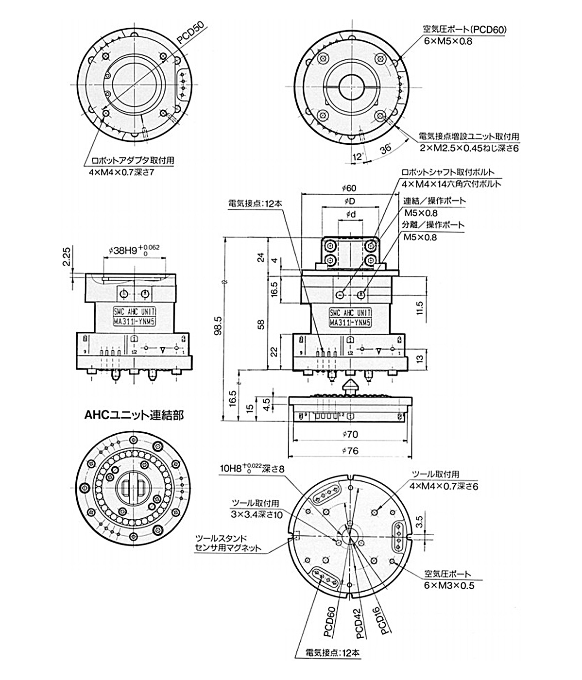
Dimensions when installed: AHC unit + tool adapter / single acting type MA310 / 320-AM3
(Unit: mm)
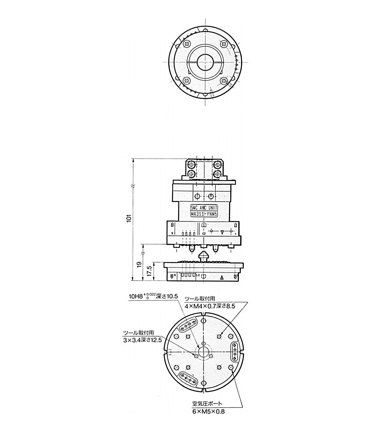
Dimensions when installed: AHC unit + tool adapter / single acting type MA310 / 320-AM5
| Model | Applicable shaft diameter ød |
øD | Weight g |
|
|---|---|---|---|---|
| AHC Unit |
MA31 0-YNM5 MA32 0-YNM5 |
– | – | 440 |
| MA31 0-YNM5-R1 MA32 0-YNM5-R1 |
10 | 35 | 520 | |
| MA31 0-YNM5-R2 MA32 0-YNM5-R2 |
11 | |||
| MA31 0-YNM5-R3 MA32 0-YNM5-R3 |
14 | |||
| MA31 0-YNM5-R4 MA32 0-YNM5-R4 |
15 | |||
| MA31 0-YNM5-R5 MA32 0-YNM5-R5 |
20 | 41 | ||
| MA31 0-YNM5-S6 MA32 0-YNM5-S6 |
24 | |||
| MA31 0-YNM5-R6 MA32 0-YNM5-R6 |
25 | |||
| For tool adapter | MA31 0-AM3 MA32 0-AM3 |
– | – | 250 |
| MA31 0-AM5 MA32 0-AM5 |
270 | |||
- *Refer to the manufacturer’s catalog for other models’ specifications, etc.
MA310-AM5
MA310-CR1
MA310-CR2
MA310-CR3
MA310-CR4
MA310-CR5
MA310-CR6
MA310-CS6
MA310-EA1
MA310-EY1
MA311-YAM5-R1
MA311-YAM5-R2
MA311-YAM5-R3
MA311-YAM5-R4
MA311-YAM5-R5
MA311-YAM5-R6
MA311-YBM5-R1
MA311-YBM5-R3
MA311-YBM5-R4
MA311-YBM5-R5
MA311-YBM5-R6
MA311-YCM5-R1
MA320-AM5
MA320-YAM5-R1
MA320-YAM5-R2
MA320-YAM5-R3
MA320-YAM5-R5
MA320-YAM5-R6
MA320-YBM5-R2
MA320-YBM5-R3
MA320-YBM5-R5
MA320-YBM5-R6
MA320-YCM5-R3
MA321-YAM5-R1
MA321-YAM5-R3
MA321-YAM5-R5
MA321-YAM5-R6
MA321-YBM5-R5
MA321-YBM5-R6
MA321-YCM5-R1
MA321-YCM5-R4
MA321-YCM5-R5
MA321-YCM5-R6
MA321-YNM5-R1
MHR2-15-A310
MHZ2-16D-A310-Y69A
MHZ2-16D-A310-Y69B
MHZ2-16D-A310-Y69BS
MHZ2-16DN-A310-Y69A
MHZ2-16DN-A310-Y69B
MHZ2-20D-A310-Y69A
MHZ2-20D-A310-Y69B
MHZ2-20D-A310-Y69BS
MHZ2-20DN-A310-Y69A
MHZ2-20DN-A310-Y69B
MHZ2-20DN-A310-Y69BS
MA310-YCM5-R5
MA310-YCM5-R6
MA310-YNM5-R1
MA310-YNM5-R2
MA310-YNM5-R3
MA310-YNM5-R4
MA310-YNM5-R5
MA310-YNM5-R6
Giới thiệu SMC Việt Nam
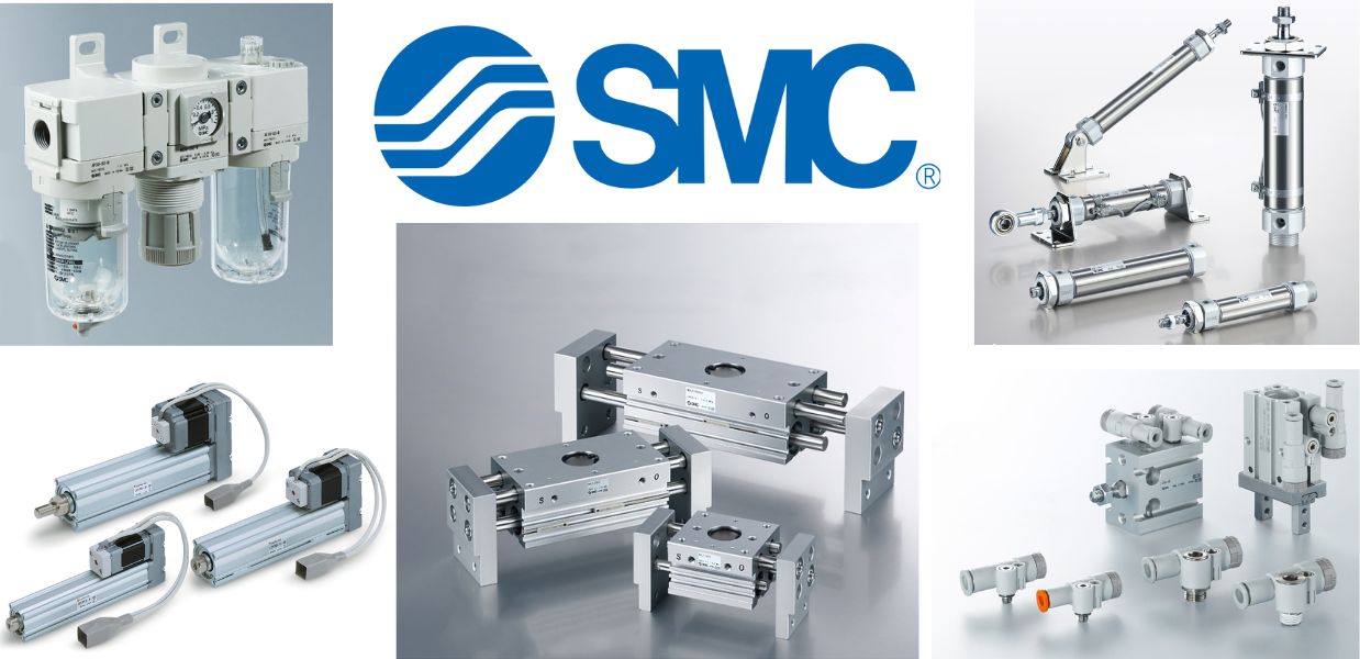
SMC là thương hiệu hàng đầu thế giới trong lĩnh vực công nghệ khí nén, cung cấp các giải pháp tiên tiến nhằm hỗ trợ tự động hóa và tối ưu hóa quy trình sản xuất.
Với nền tảng vững chắc trong ngành, SMC Việt Nam luôn đi đầu trong việc nghiên cứu, đổi mới và phát triển sản phẩm, góp phần nâng cao năng suất và tiết kiệm lao động cho các doanh nghiệp công nghiệp.
Với phương châm “đóng góp vào tự động hóa và tiết kiệm lao động trong ngành công nghiệp”, SMC Việt Nam không ngừng cải tiến và mang đến những sản phẩm công nghệ tiên tiến nhất.
SMC Việt Nam cam kết cung cấp những giải pháp hiện đại, giúp khách hàng duy trì lợi thế cạnh tranh trên thị trường.
Medin Company cung cấp các sản phẩm SMC tại Việt Nam.
Đa dạng các sản phẩm và giải pháp khí nén phục vụ cho nhiều ngành công nghiệp khác nhau, bao gồm:
- Xy lanh khí nén – Giúp kiểm soát chuyển động chính xác và hiệu quả.
- Van điện từ – Ứng dụng rộng rãi trong điều khiển luồng khí nén.
- Bộ lọc khí nén – Đảm bảo chất lượng khí nén tối ưu.
- Cảm biến và bộ điều khiển – Tăng cường tự động hóa trong quy trình sản xuất.
———————-
👉 Xem thêm sản phẩm của SMC
Liên Hệ Medin Co., Ltd
- Công ty TNHH Mễ Đình được thành lập từ năm 2006.
- Từ đó đến nay Medin luôn là Công ty dẫn đầu về lĩnh vực Tự Động Hoá ở thị trường trong và ngoài nước với hơn 1,000 khách hàng, cùng với rất nhiều dự án lớn nhỏ cho các nhà máy sản xuất.
- Chúng tôi cung cấp cho khách hàng những giải phát tuyệt vời nhất trong việc ứng dụng Tự Động Hoá vào sản xuất
- Phương châm: “Giải pháp của chúng tôi, lợi ích của khách hàng”
- Giá trị cốt lõi: “Uy tín là sự tồn tại của chúng tôi”

- Hơn 20 năm kinh nghiệm, chúng tôi có đội ngũ kỹ sư nhiều kinh nghiệm, có khả năng tư vấn, đưa ra giải pháp có lợi nhất cho khách hàng.
- Sự tin tưởng và đồng hành của khách hàng là động lực để Medin phát triển cao hơn và xa hơn.
