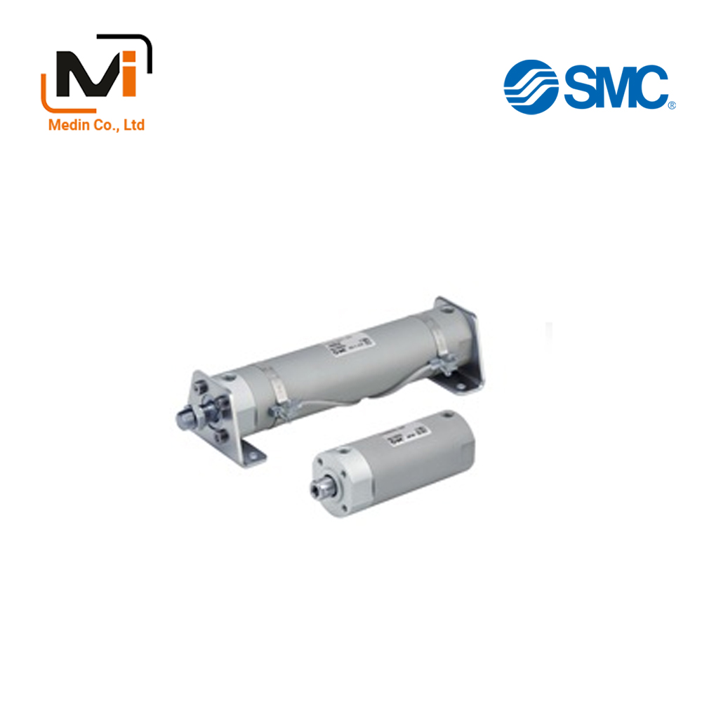
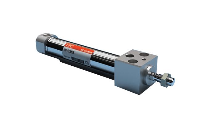
Air Cylinder, Short Type, Standard, Double Acting, Single Rod CG3 Series – Xi Lanh Khí Nén SMC
Product Description
– Xi Lanh Khí Nén SMC
A standard type short double action, single rod cylinder.
[Features]
· An air cylinder with an overall length reduced by up to 51 mm and weight reduced by up to 24% (compared to CG1).
· Female rod end available as standard.
*See the SMC catalog for specification details.
*Product pictures are representative images. CAD data is not supported for some model numbers.
Download
Air Cylinder, Short Type, Standard, Double Acting, Single Rod CG3 Series Specifications – Xi Lanh Khí Nén SMC
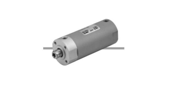
Air Cylinder, Short Type, Standard, Double Acting, Single Rod CG3 Series external appearance
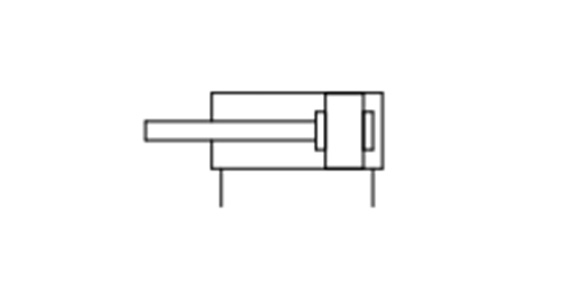
JIS symbol (rubber bumper)
Specifications
| Tube Inner Diameter (mm) | 20 | 25 | 32 | 40 | 50 | 63 | 80 | 100 | |
|---|---|---|---|---|---|---|---|---|---|
| Action | Double acting, single rod | ||||||||
| Lubrication | Not required (non-lubricated) | ||||||||
| Fluid | Air | ||||||||
| Proof Pressure | 1.0 MPa | ||||||||
| Maximum operating pressure | 0.7 MPa | ||||||||
| Minimum operating pressure | 0.05 MPa | ||||||||
| Ambient and Fluid Temperature | Without auto switch: -10°C to 70°C (No freezing) | ||||||||
| With auto switch: -10°C to 60°C (No freezing) | |||||||||
| Piston Speed | 50 to 1,000 mm/s | 30 to 700 mm/s | |||||||
| Stroke Length Tolerance | 0 to +1.4 mm | ||||||||
| Cushioning | Rubber cushion | ||||||||
| Mount Support Type | Basic type, foot type, rod-end flange type, head-end flange type, clevis type |
||||||||
| Allowable Kinetic Energy |
Rod end male thread | 0.2 J | 0.29 J | 0.46 J | 0.84 J | 1.4 J | 2.38 J | 4.13 J | 6.93 J |
| Rod end female thread | 0.11 J | 0.18 J | 0.29 J | 0.52 J | 0.91 J | 1.54 J | 2.71 J | 4.54 J | |
*Only use the cylinder within the allowable kinetic energy range. See the SMC catalog for details.
Stroke Table
| Tube Inner Diameter (mm) | Standard Stroke (mm)* |
|---|---|
| 20 | 25, 50, 75, 100, 125, 150, 200 |
| 25 | 25, 50, 75, 100, 125, 150, 200, 250, 300 |
| 32 | |
| 40 | |
| 50 | |
| 63 | |
| 80 | |
| 100 |
*Contact the SMC support center regarding intermediate strokes of 1‑mm increments. (Spacers are not used.)
Theoretical Output Table
(Unit: N)
| Tube Internal Diameter D (mm) |
Rod Diameter d (mm) |
Operating Direction | Piston Area (mm2) |
Operating Pressure (MPa) | |||||
|---|---|---|---|---|---|---|---|---|---|
| 0.2 | 0.3 | 0.4 | 0.5 | 0.6 | 0.7 | ||||
| 20 | 8 | OUT | 314 | 62.8 | 94.2 | 125.6 | 157 | 188.4 | 219.8 |
| IN | 264 | 52.8 | 79.2 | 105.6 | 132 | 158.4 | 184.8 | ||
| 25 | 10 | OUT | 491 | 98.2 | 147.3 | 196.4 | 245.5 | 294.6 | 343.7 |
| IN | 412 | 82.4 | 123.6 | 164.8 | 206 | 247.2 | 288.4 | ||
| 32 | 12 | OUT | 804 | 160.8 | 241.2 | 321.6 | 402 | 482.4 | 562.8 |
| IN | 691 | 138.2 | 207.3 | 276.4 | 345.5 | 414.6 | 483.7 | ||
| 40 | 14 | OUT | 1,257 | 251.4 | 377.1 | 502.8 | 628.5 | 754.2 | 879.9 |
| IN | 1,103 | 220.6 | 330.9 | 441.2 | 551.5 | 661.8 | 772.1 | ||
| 50 | 18 | OUT | 1,964 | 392.8 | 589.2 | 785.6 | 982 | 1,178.4 | 1,374.8 |
| IN | 1,709 | 341.8 | 512.7 | 683.6 | 854.5 | 1,025.4 | 1,196.3 | ||
| 63 | 18 | OUT | 3,117 | 623.4 | 935.1 | 1,246.8 | 1,558.5 | 1,870.2 | 2,181.9 |
| IN | 2,863 | 572.6 | 858.9 | 1,145.2 | 1,431.5 | 1,717.8 | 2,004.1 | ||
| 80 | 22 | OUT | 5,027 | 1,005.4 | 1,508.1 | 2,010.8 | 2,513.5 | 3,016.2 | 3,518.9 |
| IN | 4,646 | 929.2 | 1,393.8 | 1,858.4 | 2,323 | 2,787.6 | 3,252.2 | ||
| 100 | 26 | OUT | 7,854 | 1,570.8 | 2,356.2 | 3,141.6 | 3,927 | 4,712.4 | 5,497.8 |
| IN | 7,323 | 1,464.6 | 2,196.9 | 2,929.2 | 3,661.5 | 4,393.8 | 5,126.1 | ||
*Theoretical output (N) = Pressure (MPa) × Piston area (mm2).
Weight Table
(Unit: kg)
| Tube Inner Diameter (mm) | 20 | 25 | 32 | 40 | 50 | 63 | 80 | 100 | |
|---|---|---|---|---|---|---|---|---|---|
| Basic weight | Basic type | 0.09 | 0.14 | 0.20 | 0.32 | 0.66 | 0.92 | 1.75 | 2.74 |
| Rod-End Long Type (G) | 0.10 | 0.15 | 0.21 | 0.34 | 0.70 | 0.97 | 1.84 | 2.85 | |
| Rod End Female Thread Type (F) | 0.08 | 0.12 | 0.19 | 0.29 | 0.60 | 0.85 | 1.61 | 2.53 | |
| Additional Bracket Weight | Foot type | 0.11 | 0.13 | 0.16 | 0.22 | 0.48 | 0.72 | 0.96 | 1.75 |
| Flange type | 0.08 | 0.10 | 0.14 | 0.20 | 0.34 | 0.50 | 0.71 | 1.35 | |
| Clevis Type | 0.05 | 0.08 | 0.15 | 0.23 | 0.40 | 0.68 | 0.71 | 1.28 | |
| Pivot bracket | 0.08 | 0.09 | 0.17 | 0.25 | 0.44 | 0.80 | 0.98 | 1.75 | |
| Single Knuckle Joint | 0.05 | 0.09 | 0.09 | 0.10 | 0.22 | 0.22 | 0.39 | 0.57 | |
| Double knuckle joint (with pin) | 0.05 | 0.09 | 0.09 | 0.13 | 0.26 | 0.26 | 0.64 | 1.31 | |
| Additional weight per 50 strokes | 0.05 | 0.07 | 0.09 | 0.13 | 0.19 | 0.23 | 0.31 | 0.43 | |
| Additional Switch Magnet Weight | 0.01 | 0.01 | 0.01 | 0.01 | 0.01 | 0.02 | 0.02 | 0.04 | |
Calculation Example) CDG3FN20-100 (built-in magnet, flange type, ø20 mm, 100 stroke)
- Basic weight: 0.09 kg (basic type, ø20 mm)
- Additional bracket weight: 0.08 kg (flange type)
- Additional stroke weight: 0.05 kg / 50 mm
- Air cylinder stroke: 100 mm
- Additional switch magnet weight: 0.01 kg
0.09 + 0.08 + 0.05 × (100/50) + 0.01 = 0.28 kg
Mounting Procedure
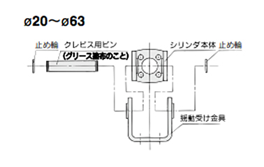
Mounting procedure for clevis: (ø20 to 63 mm)
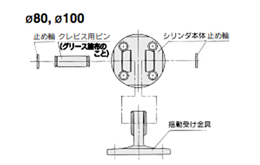
Mounting procedure for clevis: (ø80 to 100 mm)
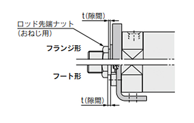
Mounting procedure for rod end nut
- *1: Tighten the clevis bracket mounting bolts to the proper tightening torques detailed below.
ø20 mm: 1.5 N·m, ø25 to 32 mm: 2.9 N·m, ø40 mm: 4.9 N·m
ø50 mm: 11.8 N·m, ø63 to 80 mm: 24.5 N·m, ø100 mm: 42.2 N·m - *2: Mount the flange type and foot type so that the distance ‘t’ (clearance) of the rod end nut is at least 1 mm.
- *3: The direction of the rod end nut (for male thread) when mounting should be with the hexagonal part at the rod end. Apply the wrench to the hexagonal part.
Diagram

With rubber bumper diagram
| Number | Name | Material | Notes |
|---|---|---|---|
| 1 | Rod cover | Aluminum alloy | Hard anodized aluminum |
| 2 | Tube Cover | Aluminum alloy | Hard anodized aluminum |
| 3 | Piston | Aluminum alloy | Chromate |
| 4 | Piston rod | Carbon steel* | Hard chrome plated* |
| 5 | Bushing | Resin/Copper alloy (Multiple layers) | – |
| 6 | Bumper A | Resin | – |
| 7 | Damper B | Resin | – |
| 8 | Wear Ring | Resin | – |
| 9 | Rod End Nut | Carbon steel | Nickel plated |
| 10 | Rod seal | NBR | – |
| 11 | Piston Seal | NBR | – |
| 12 | Tube Gasket | NBR | – |
*For cylinders with auto switches, a magnet is attached to the piston.
*The material for ø20 mm and ø25 mm cylinders with auto switches is stainless steel.
CDG3BN20-10-A93LS
CDG3BN20-10F
CDG3BN20-15-M9BL
CDG3BN20-20
CDG3BN20-20-M9B
CDG3BN20-20-M9BWZ
CDG3BN20-20F
CDG3BN20-20G-M9B3
CDG3BN20-25
CDG3BN20-25-A93
CDG3BN20-25-A93L
CDG3BN20-25-M9B
CDG3BN20-25-M9BAL-C
CDG3BN20-25-M9BL
CDG3BN25-10
CDG3BN25-10F
CDG3BN25-15
CDG3BN25-15F
CDG3BN25-20
CDG3BN25-20-M9BL
CDG3BN25-20-M9BL-C
CDG3BN25-20-M9NLS
CDG3BN25-20F
CDG3BN25-25
CDG3BN25-25-A93
CDG3BN25-25-M9B
CDG3BN25-25-M9BAL-C
CDG3BN25-25-M9BL
CDG3BN25-25-M9BLS
CDG3BN25-25-M9BM-C
CDG3BN32-10F
CDG3BN32-10G
CDG3BN32-15-M9BW-C
CDG3BN32-15F
CDG3BN32-15F-M9BL-C
CDG3BN32-15F-M9BW
CDG3BN32-15F-M9BW-C
CDG3BN32-15F-M9BWL-C
CDG3BN32-15G
CDG3BN32-15G-B54S
CDG3BN32-20
CDG3BN32-20-M9B
CDG3BN32-20-M9BL
CDG3BN32-20F
CDG3BN32-20F-M9BVL-C
CDG3BN32-20F-M9BWV-C
CDG3BN40-10F
CDG3BN40-15F
CDG3BN40-15G
CDG3BN40-15G-M9NWM-C
CDG3BN40-20
CDG3BN40-20F
CDG3BN40-25
CDG3BN40-25-A93LS
CDG3BN40-25-A93S
CDG3BN40-25-M9B
CDG3BN40-25F
CDG3BN40-25F-A93L
CDG3BN40-25F-A93M
CDG3BN40-25F-M9BMBPC
CDG3BN40-25F-M9BW
CDG3BN40-25F-M9BWL
CDG3BN50-10F
CDG3BN50-15F
CDG3BN50-20F
CDG3BN50-25
CDG3BN50-25-M9B-C
CDG3BN50-25-M9BL
CDG3BN50-25-M9BVM-C
CDG3BN50-25-M9BWS
CDG3BN50-25-M9NM
CDG3BN50-25F
CDG3BN50-25F-M9BL
CDG3BN50-25F-M9BM
CDG3BN50-25F-M9BVM-C
CDG3BN50-25F-M9BW
CDG3BN50-25F-M9BW-C
CDG3BN50-25F-M9BWM
CDG3BN63-10F
CDG3BN63-25
CDG3BN63-25-M9B
CDG3BN63-25-M9BL
CDG3BN63-25-M9BLS
CDG3BN63-25-M9BMS
CDG3BN63-25-M9BVL-C
CDG3BN63-25-M9BW
CDG3BN63-25-M9BW-C
CDG3BN63-25-M9BWL
CDG3BN63-25-M9BWSAPC
CDG3BN63-25-M9BWZ
CDG3BN63-25-M9BWZ-C
CDG3BN63-25F-M9BL
CDG3BN63-25F-M9BW
CDG3BN63-30
CDG3BN63-30F-M9BW
CDG3BN80-15
CDG3BN80-20
CDG3BN80-25
CDG3BN80-25-B54
CDG3BN80-25-K59W
CDG3BN80-25F
CDG3BN80-25G
CDG3BN80-30F
CDG3BN80-50
CDG3BN80-50-B54LS
CDG3BN80-50-G59
CDG3BN80-50-K59
CDG3BN80-50-K59L
CDG3BN80-50-K59WL
CDG3BN100-10F
CDG3BN100-25-B54
CDG3BN100-25-K59
CDG3BN100-25-K59WL
CDG3BN100-25F
CDG3BN100-25F-B54
CDG3BN100-25F-G59L
CDG3BN100-25F-K59
CDG3BN100-25F-K59W
CDG3BN100-25G-K59WL
CDG3BN100-30
CDG3BN100-30-G59L
CDG3BN100-35
CDG3BN100-50
CDG3BN100-50-K59
CDG3BN100-50-K59WS
CDG3BN100-50F

