Air-Blow Module (Straight/Elbow), LLB1 Series – Bộ lọc khí SMC
Product Description
– Bộ lọc khí SMC
Air-blow module for which short-pitch mounting is possible.
[Features]
· Reduces piping labor time and enables space saving.
· Compact integration of all devices.
· Parts in contact with fluid: Grease-free.
· Can be combined in 3 pattern variations.
· Built-in clean air filter.
· Filtration: 0.01 μm (filtration efficiency 99.99%).
· Centralized pressure control is achieved with compact design.
Download
Air-Blow Module, LLB1 Series Specifications – Bộ lọc khí SMC
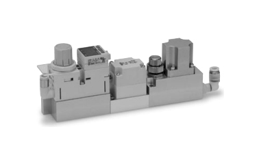
Pressure reducing valve + Digital pressure switch + ON/OFF valve + Throttle valve + Filter assembled external appearance
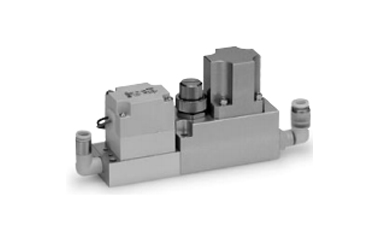
ON/OFF Valve + Throttle Valve assembled external appearance
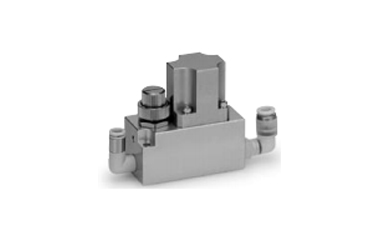
Throttle Valve + Filter assembled external appearance
Air-Blow Module Common Specifications
| Applicable Fluid | Air, N2 gas | |
|---|---|---|
| Maximum Operating Pressure | 0.7 MPa | |
| Set Pressure Range | 0.05 to 0.6 MPa (0.05 to 0.35 MPa)*3 | |
| Withstand Pressure | 1.0 MPa | |
| Working Fluid Temperature | 5 to 45°C (no freezing) | |
| Ambient Temperature | ||
| Flow Rate Range*1 | Up to 100 L/min (ANR) | |
| Filtration*2 | 0.01 μm (filtration efficiency 99.99%) | |
| Fluid Contact Space Material | Body | AL |
| Bushing | AL | |
| Packing | HNBR | |
| Fitting Material | Straight ø4 mm | POM, SUS, PBT, NBR (fluorine coating) |
| Straight ø6 mm | POM, SUS, Brass (electroless nickel plating), NBR (fluorine coating) | |
| Elbow | POM, SUS, Brass (electroless nickel plating), PBT, NBR (fluorine coating) | |
| Applicable Tubing Material | PFA, polyolefin, soft polyolefin, polyurethane*4 | |
*1: The maximum flow rate varies depending on set pressure. Refer to “Flow Rate Characteristics” graph for details.
*2: Measured under manufacturer’s specified conditions.
*3: The upper limit value of the set pressure range may vary according to the part number.
*4: Due to the softness of polyurethane material, the tube may fold when inserting. Hold the tube at the end and insert securely all the way in.
Pressure Reducing Valve Unit Specifications
| Pressure Reducing Valve Structure | Direct acting | |
|---|---|---|
| Relief Structure | Relief type | |
| Pressure Gauge Specifications | Display Accuracy | ±3% F.S. (full span) |
| Calibration Angle | 230 ° | |
| Limit Indicator | Yes | |
| Fluid Contact Space Material | Body, Port Plug | PBT |
| Valve Seat, Stem | POM | |
| Diaphragm | Weatherproof NBR | |
| Valve | Aluminum alloy (chromate), HNBR | |
| Valve Spring | SUS | |
| O-ring | HNBR | |
| Without Pressure Display Function | POM, HNBR | |
| With Pressure Gauge | Brass, HNBR | |
| Digital Pressure Switch | PPS, Silicone, HNBR | |
ON/OFF Valve Unit Specifications
| Valve Structure | Pilot-operated 2-port poppet type | |
|---|---|---|
| Ambient and Fluid Temperature | -10 to +50°C*1 | |
| Impact Resistance/Vibration Resistance | 150/30 m/s2*2 | |
| Internal Leakage cm3/min | 15 or less | |
| External Leakage cm3/min | 15 or less | |
| Mounting Orientation | Free | |
| Coil Rated Voltage | 12 V DC, 24 V DC | |
| Allowable Voltage Fluctuation | ±10% of rated voltage | |
| Coil Insulation Type | Equivalent to B type | |
| Power Consumption | V5, V6 | Inrush: 2.9 W Holding: 0.6 W |
| V5E | 1.8 W | |
| Lead Wire Electrical Entry Method | Grommet | |
| Flow Rate Characteristics | C [dm3/(s·bar)] | V5, V6: 1.4, V5E: 0.71 |
| b | V5, V6: 0.23, V5E: 0.25 | |
| Cv | V5, V6: 0.33, V5E: 0.17 | |
| Minimum Operating Pressure Differential | 0.01 MPa*3 | |
| Maximum Operating Pressure | 0.6 MPa | |
| Response Time*4 | ON | 10 ms or less (with power-saving circuit) |
| OFF | 15 ms or less (with power-saving circuit) | |
| Fluid Contact Space Material | Body | PBT |
| Diaphragm | HNBR | |
| Movable/Fixed Armature | SUS | |
*1: Use dry air to prevent condensation when operating at low temperatures.
*2: Vibration resistance: No malfunction occurred under any of the conditions tested in a one-sweep test between 8.3 to 2,000 Hz. Test was performed in axial and orthogonal directions to the main valve/movable armature at both energized and de-energized states. (Value at the initial state)
Impact resistance: No malfunction resulted from the impact test using a drop impact tester under any of the conditions tested. The test was performed once for each set of conditions, in axial and orthogonal directions to the main valve/movable armature at both energized and de-energized states. (Value at the initial state)
*3: If a throttle (nozzle, etc.) is mounted on the outlet side piping, the pressure differential when ON is smaller. Ensure that the pressure differential does not drop below 0.01 MPa.
*4: JIS8375 (at supply pressure of 0.5 MPa) (Numerical value of response time varies according to pressure and quality of air.)
Throttle Valve Unit Specifications
- Cv factor: 0.28
- Number of needle rotations: 8 rotations
- Fluid contact space material: SUS
Filter Unit Specifications
- Filtration (*1): 0.01 μm (filtration efficiency 99.99%)
- Element proof differential pressure (*2): 0.5 MPa
- Air processing flow rate: Up to 100 L/min (ANR)
- *1Measured under manufacturer’s specified conditions.
- *2This means that the element will not break at 0.5 MPa. Refer to installation precautions prior to use.
Fluid Contact Space Material
- Filter case: PC/ABS
- Hollow fiber: PP/PET
- Potting: PU
- O-ring: FKM
Product Outline Dimensional Drawing
(Unit: mm)
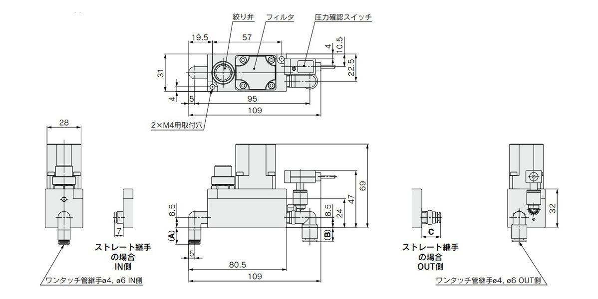
LLB1-(C4□/C6□)-F(1)-X1 dimensional drawing
- Fitting size ø4 mm: A / 13 mm, B / 12.2 mm, C / 20.5 mm
- Fitting size ø6 mm: A / 13.5 mm, B / 14.3 mm, C / 21 mm
(Unit: mm)
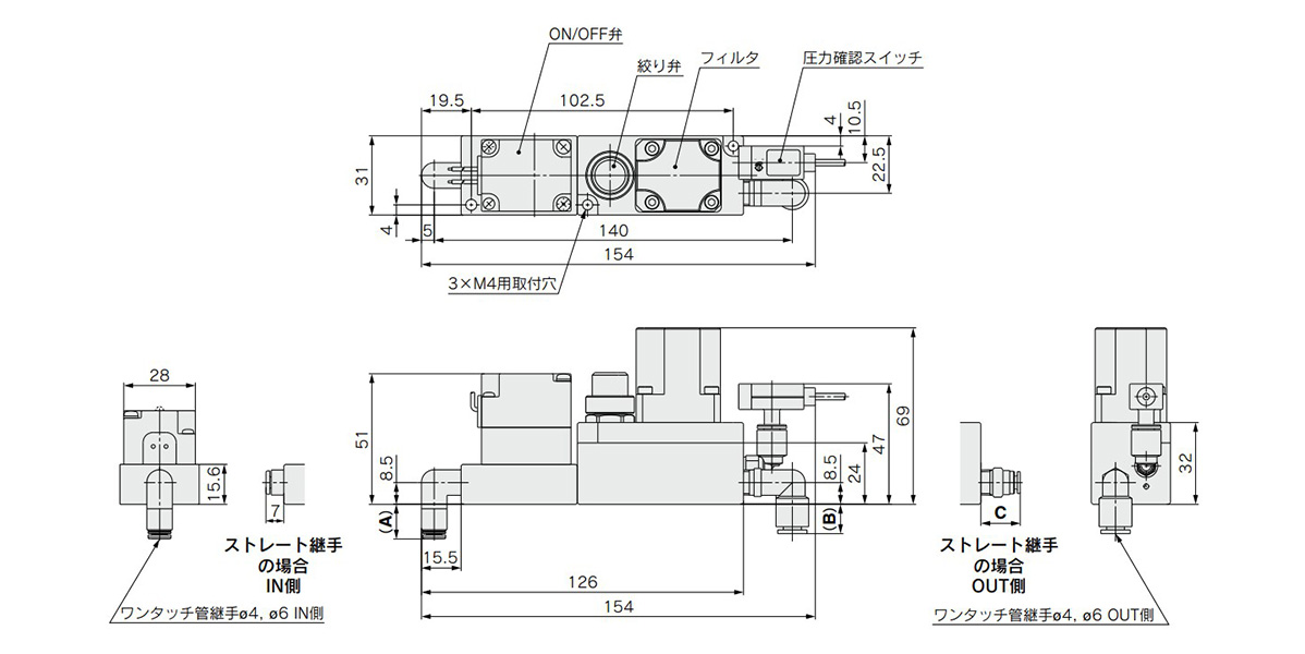
LLB1-(C4□/C6□)-(V5F/V6F)(1)-X1
- Fitting size ø4 mm: A / 13 mm, B / 12.2 mm, C / 20.5 mm
- Fitting size ø6 mm: A / 13.5 mm, B / 14.3 mm, C / 21 mm
(Unit: mm)
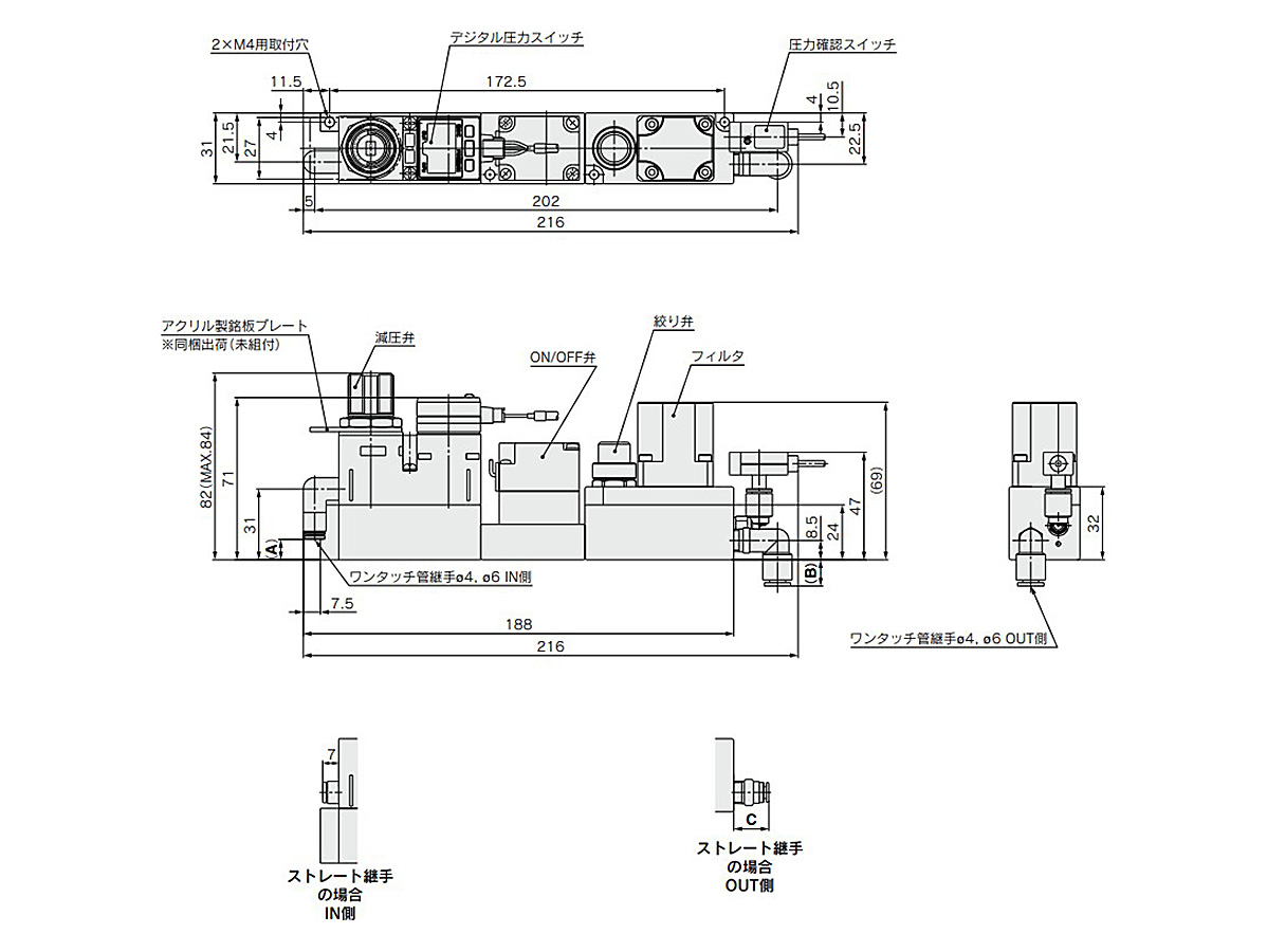
LLB1-(C4□/C6□)-(RN□/RP□/RG□)(V5F/V6F)(1)-X1
*Acrylic name plate: Shipped together (unassembled)
- Fitting ø4 mm: A / 9.5 mm, B / 12.2 mm, C / 20.5 mm
- Fitting size ø6 mm: A / 9 mm, B / 14.3 mm, C / 21 mm
Component Parts
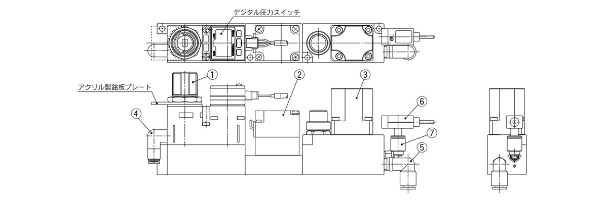
LLB1 Series component parts
(Unit: mm)
| No. | Description | Note | ||
|---|---|---|---|---|
| 1 | Pressure reducing valve ass’y | Without pressure gauge | – | |
| With digital pressure switch | For set pressure range 0 to 0.35 MPa: LVB1-2-2 | |||
| NPN open collector | ||||
| With digital pressure switch | For set pressure range 0 to 0.35 MPa: LVB1-3-2 | |||
| PNP open collector | ||||
| With Pressure Gauge | For set pressure range 0 to 0.35 MPa: LVB1-4-2 | |||
| Acrylic name plate | – | |||
| 2 | ON/OFF valve | 12 V DC | – | |
| 24 V DC (2.9 W) | ||||
| 24 V DC (1.8 W) | ||||
| 3 | Clean air filter ass’y with throttle valve | Replacement element | – | |
| 4 | IN side single-action fitting ass’y | Straight | ø4 mm | – |
| ø6 mm | ||||
| Elbow | ø4 mm | |||
| ø6 mm | ||||
| 5 | OUT side single-action fitting ass’y | Straight | ø4 mm | – |
| ø6 mm | ||||
| Elbow | ø4 mm | |||
| ø6 mm | ||||
| 6 | Pressure check switch | – | ||
| 7 | Fitting for pressure check switch | – | ||
Product Flow Rate Characteristics
Conditions
- 1. ø6 mm tube length: measured at IN side = 600 mm / OUT side = 100 mm.
- 2.Measured with regulator fully open.
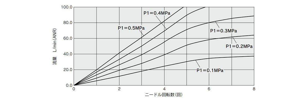
Relationship between number of needle rotations and flow rate
*The flow rate characteristics are representative values.
Precautions
- *Ensure that you read the specific product precautions prior to use.
- *See the manufacturer’s catalog for product information other than the above.
- *Product pictures are example representations for the product series. Please be aware that actual product specifications may be different.
Design and Selection
- *Confirm the specifications: Give due consideration to the operating conditions such as the application, fluid and environment, and use within the operating ranges specified in the manufacturer’s catalog.
- *Ensure sufficient maintenance space: Provide the required space for maintenance inspection.
- *Fluid pressure range: Supplied fluid pressure must be within the operating pressure range specified in the manufacturer’s catalog.
Mounting
- *If air leakage increases, or equipment does not operate correctly, stop use immediately.
- *After mounting, perform suitable function and leak testing to confirm that the mounting is correct.
LLB1-C4-RGV5EF1-X1
LLB1-C4-RGV5EF-X1
LLB1-C4-RGV5F1-X1
LLB1-C4-RGV5F-X1
LLB1-C4-RN5V5F1-X1
LLB1-C4-RNV5EF1-X1
LLB1-C4-RNV5F1-X1
LLB1-C4-RNV5F-X1
LLB1-C4-RV6F-X1
LLB1-C4-V5EF-X1
LLB1-C4-V5F-X1
LLB1-C4L-F-X1
LLB1-C4L-RG5V5EF-X1
LLB1-C4L-RGV5F-X1
LLB1-C4L-V5F-X1
LLB1-C6-F1-X1
LLB1-C6-F-X1
LLB1-C6-RG5V5F-X1
LLB1-C6-RGV5EF-X1
LLB1-C6-RGV5F1-X1
LLB1-C6-RGV5F-X1
LLB1-C6-RN5V5EF-X1
LLB1-C6-RN5V5F-X1
LLB1-C6-RNV5EF1-X1
LLB1-C6-RNV5EF-X1
LLB1-C6-RNV5F1-X1
LLB1-C6-RNV5F-X1
LLB1-C6-RV5F-X1
LLB1-C6-V5EF-X1
LLB1-C6-V5F1-X1
LLB1-C6-V5F-X1
LLB1-C6L-F1-X1
LLB1-C6L-F-X1
LLB1-C6L-RG5V5EF1-X1
LLB1-C6L-RG5V5EF-X1
LLB1-C6L-RG5V5F-X1
LLB1-C6L-RGV5EF1-X1
LLB1-C6L-RGV5EF-X1
LLB1-C6L-RGV5F1-X1
LLB1-C6L-RGV5F-X1
LLB1-C6L-RN5V5EF1-X1
LLB1-C6L-RN5V5EF-X1
LLB1-C6L-RN5V5F1-X1
LLB1-C6L-RN5V5F-X1
LLB1-C6L-RNV5EF1-X1
LLB1-C6L-RNV5EF-X1
LLB1-C6L-RNV5F1-X1
LLB1-C6L-RNV5F-X1
LLB1-C6L-RV5F-X1
LLB1-C6L-V5EF1-X1
LLB1-C6L-V5EF-X1
LLB1-C6L-V5F1-X1
LLB1-C6L-V5F-X1
LVB1-1
LVB1-2-1
LVB1-2-2
LVB1-3-1
