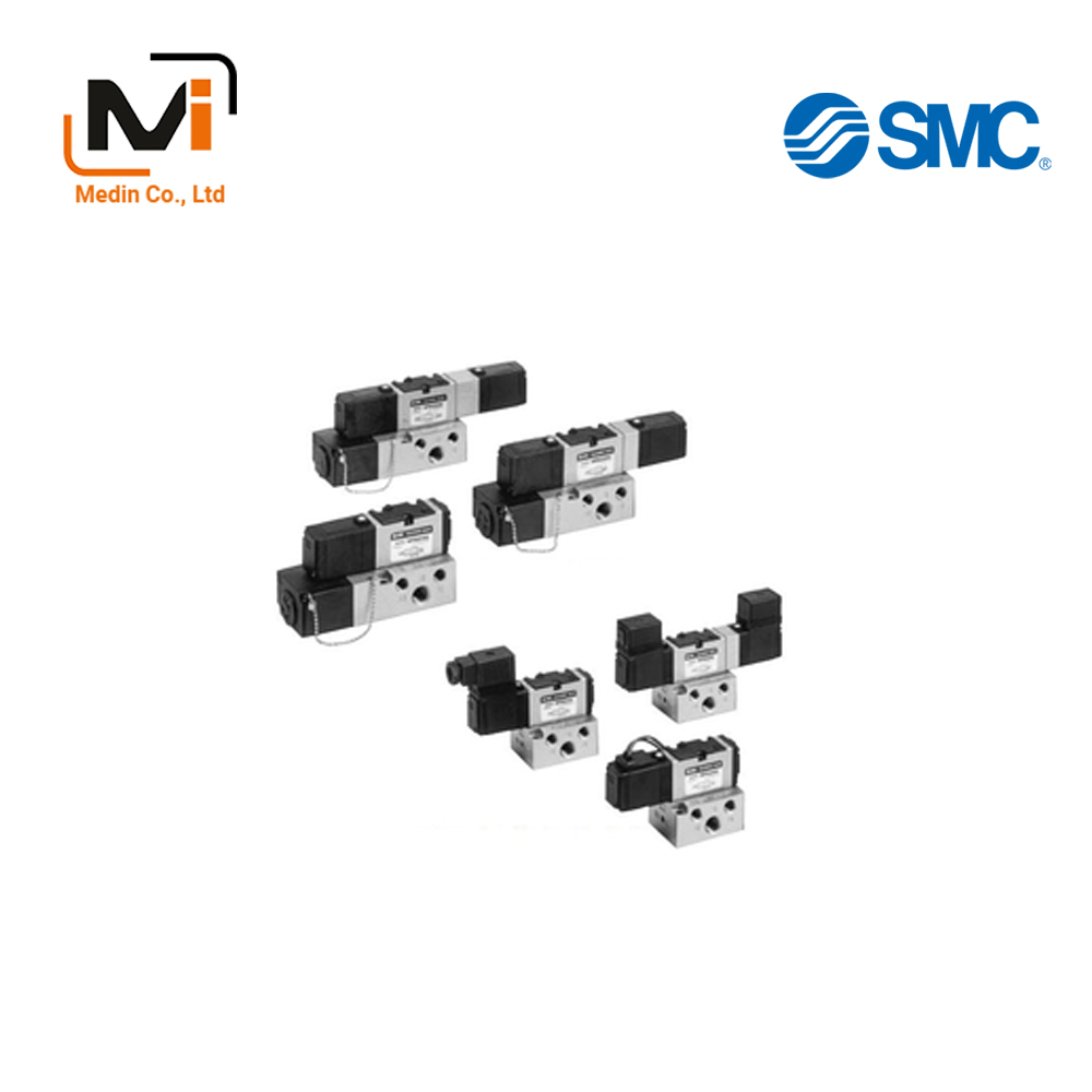
5-Port Solenoid Valve, Pilot Operated, Metal Seal, VFS2000 – Van Điện Từ SMC
Product Description
– Van Điện Từ SMC
SMC Solenoid Valve.
[Features]
· Large valve capacity 1/4: C: 2.8 dm3/(s·bar)
· Low power consumption: 1.8 W DC
· Easy maintenance and inspection
· 2 types of subplate, plug-in type and non-plug-in type.
Download
Metal Seal, 5-Port Pilot Type, Plug-In Type / Non-Plug-In Type VFS2000 Series Specifications – Van Điện Từ SMC
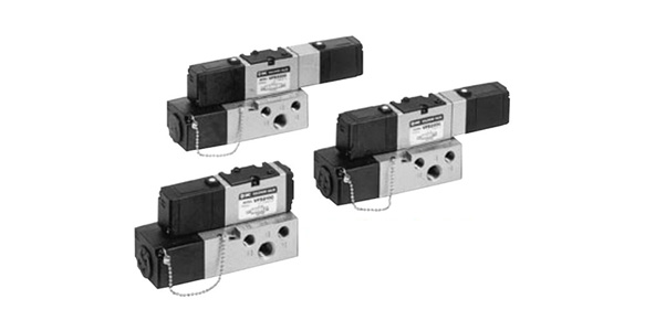
VFS2000 Series plug-in type external appearance
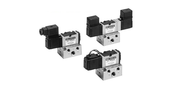
VFS2000 Series non-plug-in type external appearance
| Valve Specifications | Fluid | Air | ||
|---|---|---|---|---|
| Maximum Operating Pressure | 1.0 MPa | |||
| Minimum Operating Pressure | 2 Position | 0.1 MPa | ||
| 3 Position | 0.15 MPa | |||
| Guaranteed Proof Pressure | 1.5 MPa | |||
| Ambient Temperature and Operating Fluid Temperature | *1 -10 to 60°C | |||
| Lubrication | *2 Not required | |||
| Pilot Valve – Manual Operation | Non-locking push type (flush) | |||
| Impact Resistance / Vibration Resistance | *3 150/50 m/s2 | |||
| Enclosure | *4 G/E type: dust-proof (IP50 equivalent), F/T/D type: splash-proof (IP54 equivalent) *6 | |||
| Electrical Specifications | Coil Rated Voltage | 100 V, 200 V AC (50/60 Hz), 24 V DC | ||
| Allowable Voltage Fluctuation | -15% to +10% of rated voltage | |||
| Coil Insulation Type | *5 Class B or equivalent (130°C) | |||
| Apparent Power (Power Consumption) AC | Starting | 5.6 VA / 50 Hz, 5.0 VA / 60 Hz | ||
| Holding | 3.4 VA (2.1 W) / 50 Hz, 2.3 VA (1.5 W) / 60 Hz | |||
| Current Consumption DC | 1.8 W (2.04 W: with light and surge voltage suppressor) | |||
| Electrical Entry | Plug-in type | Conduit terminal | ||
| Non-plug-in type | Grommet terminal, DIN terminal | |||
*1: Use dry air when at low temperatures.
*2: If lubricating, use turbine oil class 1 (ISO VG32).
*3: Impact resistance: No malfunctions after testing using a drop-type impact tester under the following conditions: in the axial direction and at a right angle to the main valve and armature in both energized and non-energized states (once for each condition state). (Initial value)
Vibration resistance: No malfunctions occurred in a 1-sweep test between 45 and 2,000 Hz. The test was performed in both energized and non-energized states and in the axial direction and at right angles to the main valve and armature. (Initial value)
*4: Based on JlS C 0920.
*1: Based on JIS C 4003.
*6: Type F protective structure indicates no light or surge voltage suppressor. Those with a light and surge voltage suppressor are IP50 equivalent.
| Pilot Method | *External pilot type |
|---|---|
| Manual Operation | Non-locking push type (extended), locking type (tool required), locking type (lever) |
| Coil Rated Voltage | 110 to 120 V, 220 V to 240 V AC 50/60 Hz |
| 12 V, 100 V DC | |
| Piping Specifications | Bottom piping type |
| Options | With light and surge voltage suppressor |
*Operating pressure: 0 to 1 MPa / Pilot pressure: (2-position) 0.1 to 1 MPa / (3-position) 0.15 to 1 MPa
Model
| Configuration | Model | Pipe connection Port diameter Rc |
Flow Rate Characteristics | *1: Maximum Operating Frequency CPM |
*2: Response Time ms |
*3: Weight kg |
|||||||
|---|---|---|---|---|---|---|---|---|---|---|---|---|---|
| Plug-In | Non-Plug-In | 1 → 4/2 (P → A/B) | 4/2 → 5/3 (A/B → R1/R2) | ||||||||||
| C (dm3/(s·bar)) |
b | Cv | C (dm3/(s·bar)) |
b | Cv | ||||||||
| 2 Position | Single | VFS2100 | VFS2110 | 1/8 | 2.4 | 0.16 | 0.55 | 2.8 | 2.20 | 0.65 | 1,200 | 15 or less | 0.34 |
| 1/4 | 2.5 | 0.18 | 0.58 | 2.8 | 0.21 | 0.65 | |||||||
| Double | VFS2200 | VFS2210 | 1/8 | 2.4 | 0.16 | 0.55 | 2.8 | 0.20 | 0.65 | 1,200 | 13 or less | 0.42 | |
| 1/4 | 2.5 | 0.18 | 0.58 | 2.8 | 0.21 | 0.65 | |||||||
| 3 Position | Closed Center | VFS2300 | VFS2310 | 1/8 | 2.3 | 0.14 | 0.53 | 2.6 | 0.20 | 061 | 600 | 20 or less | 0.43 |
| 1/4 | 2.5 | 0.18 | 0.58 | 2.6 | 0.23 | 0.62 | |||||||
| Exhaust Center | VFS2400 | VFS2410 | 1/8 | 2.4 | 0.15 | 0.54 | 2.7 | 0.25 | 0.63 | 600 | 20 or less | 0.43 | |
| 1/4 | 2.5 | 0.20 | 0.60 | 2.7 | 0.24 | 0.63 | |||||||
| Pressure Center | VFS2500 | VFS2510 | 1/8 | 2.5 | 0.11 | 0.55 | 2.7 | 0.20 | 0.62 | 600 | 20 or less | 0.43 | |
| 1/4 | 2.8 | 0.17 | 0.63 | 2.7 | 0.22 | 0.63 | |||||||
| Perfect | VFS2600 | VFS2610 | 1/8 | 1.2 | – | – | 1.3 | – | – | 600 | 25 or less | 0.6 | |
| 1/4 | 1.2 | – | – | 1.3 | – | – | |||||||
*1: The minimum operating frequency is according to JIS B 8419:2010 (once per 30 days).
*2: According to JIS B 8419:2010 (value with supply pressure of 0.5 MPa).
*3: Value for VFS2□00-□FZ-01.
*4: *1 and *2 assume controlled clean air.
SF4-1DA-20
SF4-1DB-20
SF4-1DC-20
SF4-1DO-20
SF4-1DOA-20
SF4-1DOB-20
SF4-1DOC-20
SF4-1DOZ-20
SF4-1DOZA-20
SF4-1DOZB-20
SF4-1DOZC-20
SF4-1DZA-20
SF4-1DZB-20
SF4-1DZC-20
SF4-1E-20
SF4-1EA-20
SF4-1EB-20
SF4-1EC-20
SF4-1EZ-20
SF4-1EZA-20
SF4-1EZB-20
SF4-1EZC-20
SF4-1FA-20
SF4-1TZ-20
SF4-1TZA-20
SF4-1TZB-20
SF4-1TZC-20
SF4-1Y-20
SF4-1YA-20
SF4-1YB-20
SF4-1YC-20
SF4-1YO-20
SF4-1YOA-20
SF4-1YOB-20
SF4-1YOC-20
SF4-1YOZ-20
SF4-1YOZA-20
SF4-1YOZB-20
SF4-1YOZC-20
SF4-1YZ-20
SF4-1YZA-20
SF4-1YZB-20
SF4-1YZC-20
SF4-2D-20
SF4-2DA-20
SF4-2DB-20
VFS2100-1F-01
VFS2100-1F-02
VFS2100-1F-BP02
VFS2100-1F-P01
VFS2100-1F-P02
VFS2100-1F-Q
VFS2100-1FA
VFS2100-1FA-02
VFS2100-1FB
VFS2100-1FB-01
VFS2100-1FB-02
VFS2100-1FC
VFS2100-1FC-01
VFS2100-1FC-02
VFS2100-1FZ
VFS2100-1FZ-01
VFS2100-1FZ-01-Q
VFS2100-1FZ-01F
VFS2100-1FZ-01N
VFS2100-1FZ-01T
VFS2100-1FZ-02
VFS2100-1FZ-02-Q
VFS2100-1FZ-02F
VFS2100-1FZ-02T
VFS2100-1FZ-B01
VFS2100-1FZ-B02
VFS2110-1D-01
VFS2110-1D-01-Q
VFS2110-1D-01T
VFS2110-1D-02
VFS2110-1D-02N
VFS2110-1D-B02
VFS2110-1D-Q
VFS2110-1D-S01
VFS2110-1D-S02
VFS2110-1DA
VFS2110-1DA-01
VFS2110-1DA-02
VFS2110-1DB
VFS2110-1DB-02
VFS2110-1DC
VFS2110-1DC-01
VFS2110-1DC-02
VFS2110-1DO
VFS2110-1DZ
VFS2110-1DZ-01
VFS2110-1DZ-01F
VFS2110-1DZ-02
VFS2110-1DZ-02-Q

