3‑Port Direct Operated Solenoid Valve – Metal Seal VS3135/3145 Series – Van Điện Từ SMC
Product Description
– Van Điện Từ SMC
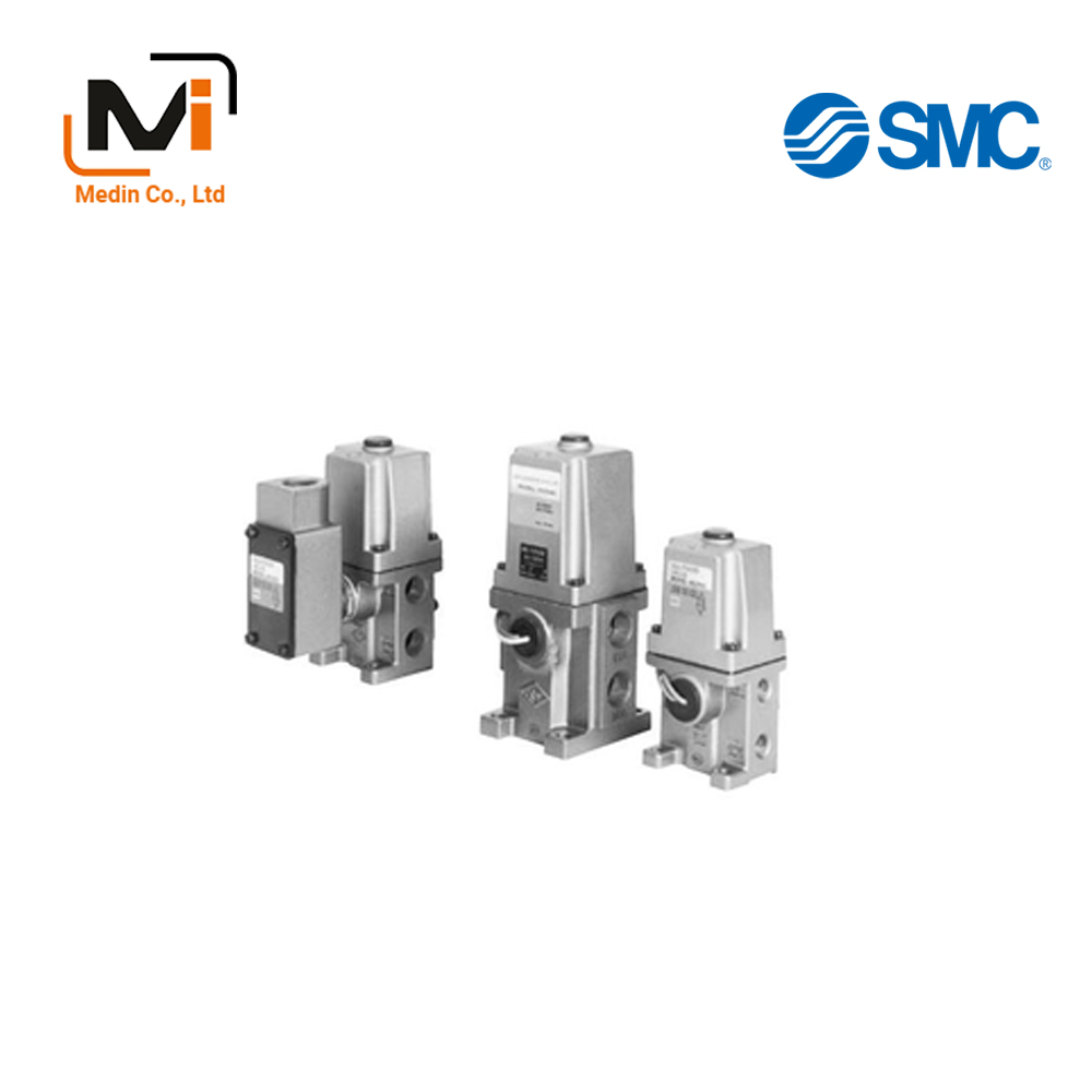
The main valve structure is a metal seal type solenoid valve.
[Features]
・ Direct acting solenoid valve
・ Pressure can be used from 0 MPa
・ Different pressures can be supplied
・ Manifold model: VVS310, VVS311
・ Body size: 3/8 standard (VS3135), 1/2 standard (VS3145)
・ Screw type: Rc, NPT, NPTF, G
・ Option: None, manual (Locking type)
Download
3-Port Solenoid Valve, Direct Operated Type, VS3135/VS3145 Series, Metal Seal Specifications – Van Điện Từ SMC
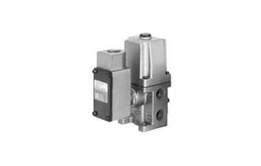
VS3135/VS3145 Series terminal type external appearance
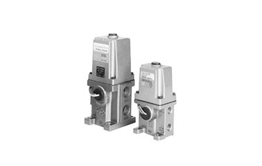
VS3135/VS3145 Series external appearance
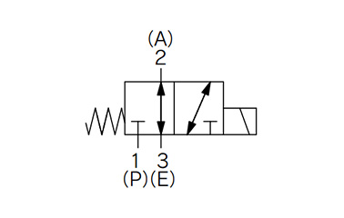
VS3135/VS3145 Series JIS symbol
| Fluid | Air, inert gases | |
|---|---|---|
| Operating Pressure | 1.5 MPa | |
| Guaranteed Proof Pressure | 0 to 1.0 MPa | |
| *1: Ambient Temperature and Operating Fluid Temperature °C | -20 to 60 | |
| *2: Lubrication | Not required | |
| Manual Operation | Non-locking type available (manual is optional) | |
| Electrical Entry | Grommet, terminal conduit Drip-proof terminal conduit |
|
| Coil Rated Voltage | AC | 100, 200 V 50/60 Hz |
| DC | 24 V | |
| Allowable Voltage Fluctuation | -15% to 10% of rated voltage | |
| Coil Insulation Type | *3: Class B or equivalent (130°C) | |
| Impact Resistance / Vibration Resistance: m/s2 | *4: 150/50 | |
*1: In low temperatures, dry air is required. (no freezing)
*2: If lubricating, use turbine oil class 1 (ISO VG32).
*3: Based on JIS C 4003.
*4: Impact resistance: No malfunctions after testing using a drop-type impact tester under the following conditions: in the axial direction and at a right angle to the main valve and armature in both energized and non-energized states (once for each condition state). (Initial value)
Vibration resistance: No malfunctions occurred in a 1-sweep test between 45 and 2,000 Hz. The test was performed in both energized and non-energized states and in the axial direction and at right angles to the main valve and armature. (Initial value)
Model
| Model | VS3135 | VS3145 | |||||||||||||
|---|---|---|---|---|---|---|---|---|---|---|---|---|---|---|---|
| Flow Rate Characteristics | P → A | A → E | P → A | A → E | |||||||||||
| C (dm3 (s·bar)] | b | Cv | C (dm3 (s·bar)] | b | Cv | C (dm3 (s·bar)] | b | Cv | C (dm3 (s·bar)] | b | Cv | ||||
| 1/4 | 6.1 | 0.3 | 1.5 | 6.1 | 0.4 | 1.6 | – | – | – | – | – | – | |||
| 3/8 | 7.2 | 0.2 | 1.8 | 7.3 | 0.2 | 1.8 | – | – | – | – | – | – | |||
| 1/2 | 9.0 | 0.2 | 2.3 | 9.0 | 0.3 | 2.4 | 18 | 0.27 | 4.8 | 16 | 0.34 | 4.1 | |||
| 3/4 | – | – | – | – | – | – | 20 | 0.21 | 5.1 | 15 | 0.46 | 4.5 | |||
| *1: Response Time ms | AC | 30 or less | 30 or less | ||||||||||||
| DC | 60 or less | 80 or less | |||||||||||||
| *2: Maximum Operating Frequency CPM | AC | 300 or less | 180 or less | ||||||||||||
| DC | 180 or less | 180 or less | |||||||||||||
| Weight kg | AC | 0.8 | 1.6 | ||||||||||||
| DC | 1.1 | 2.4 | |||||||||||||
| Apparent Power VA | AC | Starting | 50 HZ | 100 | 300 | ||||||||||
| 60 HZ | 90 | 360 | |||||||||||||
| Holding | 50 HZ | 20 | 50 | ||||||||||||
| 60 HZ | 14 | 60 | |||||||||||||
| Power Consumption W | DC | 13.2 | 24 | ||||||||||||
*1: Based on JIS B 8375-1981. At 0.5 MPa with no surge voltage suppressor.
*2: The minimum operating frequency is according to JIS B 8375 (once per 30 days).
*3: *1 and *2 assume controlled clean air.
VS3135-021-N
VS3135-021-T
VS3135-021P
VS3135-021P-N
VS3135-021T
VS3135-021TL
VS3135-021TL-N
VS3135-021TLP
VS3135-021TLZ
VS3135-021TLZP
VS3135-021TP
VS3135-021TP-N
VS3135-021TZ
VS3135-021TZP
VS3135-021WT
VS3135-021WTB
VS3135-021WTB-N
VS3135-021WTBL-N
VS3135-021WTBP
VS3135-021WTL
VS3135-022TZP
VS3135-022WT
VS3135-022WTB
VS3135-022WTBLZP
VS3135-022WTBP
VS3135-022WTL
VS3135-022WTLZ
VS3135-022WTZ
VS3135-023
VS3135-023-N
VS3135-023-T
VS3135-023P
VS3135-023P-N
VS3135-023P-T
VS3135-023T
VS3135-023T-N
VS3135-023TL
VS3135-023TLP
VS3135-023TLP-N
VS3145-041-N
VS3145-041-T
VS3145-041P
VS3145-041P-N
VS3145-041T
VS3145-041T-F
VS3145-041TL
VS3145-041TLP
VS3145-041TLZ
VS3145-041TLZP
VS3145-041TP
VS3145-041TZ
VS3145-041TZ-N
VS3145-041TZP
VS3145-041WTB
VS3145-041WTB-N
VS3145-041WTBL
VS3145-041WTBP
VS3145-041WTL
VS3145-041WTLZ
VS3145-041WTLZ-N
VS3145-042TZ-N
VS3145-042TZP
VS3145-042WTB
VS3145-042WTBL
VS3145-042WTBP
VS3145-042WTL
VS3145-043
VS3145-043-N
VS3145-043-T
VS3145-043P
VS3145-043P-T
VS3145-043T
VS3145-043T-N
VS3145-043T-T
VS3145-043TL
VS3145-043TL-N
VS3145-043TLP
VS3145-043TLP-F
VS3145-043TLP-N
VS3145-043TP

