2-Color Display Digital Flow Switch, Integrated Display Type PFM7 Series – Cảm Biến Áp Suất SMC
Product Description
– Cảm Biến Áp Suất SMC
A flow switch made by SMC.
[Features]
· 2-color display digital flow switch
· Fluid: air, N2, Ar, CO2
· Flow rate range: 10, 25, 50,100 L/min
· Minimum set unit: 0.01 L/min (flow rate range of 25, 50, 100 L/min is 0.1 L/min)
· Repeatability: ±1% F.S.
· Grease-free
· Integrated flow rate adjustment valve (reduces piping, saves space)
· Response time: 50 ms, 0.5 s, 1 s, 2 s can be selected
Download
Specifications of 2-Color Display Digital Flow Switch, Integrated Display Type PFM7 Series – Cảm Biến Áp Suất SMC
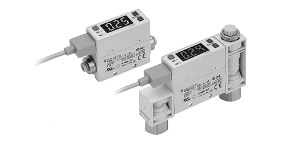
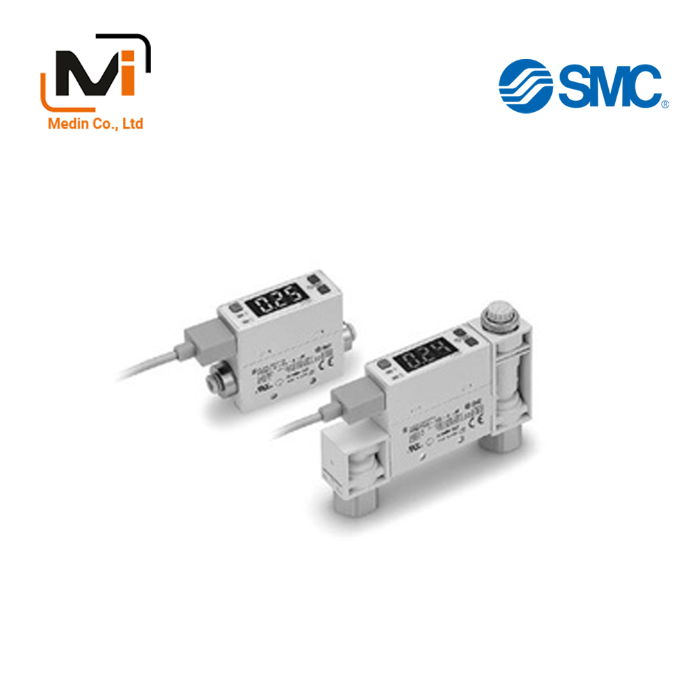
External appearance of PFM7 Series
Features
- Minimum Unit Setting: 0.01 L/min (0.1 L/min for the flow rate range of 25 L/min, 50 L/min, 100 L/min)
- Small: Same size for each flow rate range (10 L/min, 25 L/min, 50 L/min, 100 L/min).
- Lightweight: 55 g (PFM711 with quick-connect fitting, without flow control valve) (Conventional model PF2A711: 290 g)
- Since the straight pipe part* is not required, it can be installed in a narrow space.
* In the case of the conventional model, it is necessary to provide a straight pipe part 8 times the pipe diameter.
Specifications
| Model | PFM710 | PFM725 | PFM750 | PFM711 | |
|---|---|---|---|---|---|
| Fluid | Dry air, N2, Ar, CO2 (Air quality classes are JIS B8392-1 1.1.2 to 1.6.2, ISO8573-1 1.1.2 to 1.6.2) |
||||
| Rated flow rate range (Flow rate range) | Dry air, N2, Ar | 0.2 to 10 L/min | 0.5 to 25 L/min | 1 to 50 L/min | 2 to 100 L/min |
| CO2 | 0.2 to 5 L/min | 0.5 to 12.5 L/min | 1 to 25 L/min | 2 to 50 L/min | |
| Displayable range *1) | Dry air, N2, Ar | 0.2 to 10.5 L/min | 0.5 to 26.3 L/min | 1 to 52.5 L/min | 2 to 105 L/min |
| CO2 | 0.2 to 5.2 L/min | 0.5 to 13.1 L/min | 1 to 26.2 L/min | 2 to 52 L/min | |
| Settable range *1) | Dry air, N2, Ar | 0 to 10.5 L/min | 0 to 26.3 L/min | 0 to 52.5 L/min | 0 to 105 L/min |
| CO2 | 0 to 5.2 L/min | 0 to 13.1 L/min | 0 to 26.2 L/min | 0 to 52 L/min | |
| Minimum unit setting *2) | 0.01 L/min | 0.1 L/min | 0.1 L/min | 0.1 L/min | |
| Flow rate conversion value of accumulated pulse | 0.1 L/Pulse | 0.1 L/Pulse | 0.1 L/Pulse | 1 L/Pulse | |
| Display unit *3) | Instantaneous flow rate L/min, CFM × 10^-2 Accumulated flow rate L, ft3× 10^-1 |
||||
| Accuracy | Display accuracy: ±3%F.S. (Fluid: In dry air) Analog output accuracy: ±5%F.S. (Fluid: In dry air) |
||||
| Repeatability | ±1%F.S. (Fluid: In dry air) Analog output: ±3%F.S. (Fluid: In dry air) |
||||
| Pressure characteristic | ±5%F.S. (0.35 MPa reference) | ||||
| Temperature characteristics | ±2%F.S. (15 to 35℃) ±5%F.S. (0 to 50℃) |
||||
| Operating Pressure Range | -100 kPa to 750 kPa | ||||
| Rated pressure range | -70 kPa to 750 kPa | ||||
| Withstand pressure | 1 MPa | ||||
| Accumulated Flow Rate Range | Maximum 999,999 L *4) | ||||
| Switch output | – | NPN or PNP open collector output | |||
| Maximum load current | 80 mA | ||||
| Maximum applied voltage | DC28V (At the time of NPN output) | ||||
| Internal Voltage Drop | NPN output: 1 V or less (at 80 mA) PNP output: 1.5 V or less (at 80 mA) | ||||
| Response Time | 1s (50 ms, 0.5 s, 2 s selectable) | ||||
| Output protection | Short-circuit protection | ||||
| Accumulated pulse output | NPN or PNP open collector output (Same as switch output) | ||||
| Analog output *5) | Response Time | 1.5 s or less (90% response) | |||
| Voltage Output | Output voltage: 1 to 5 V Output Impedance: 1 kΩ |
||||
| Current Output | Output current: 4 to 20 mA Maximum load impedance: 600 Ω, minimum load impedance: 50 Ω |
||||
| Hysteresis *6) | Hysteresis mode | Variable | |||
| Window Comparator Mode | Variable | ||||
| External input | Dry input (contact or non-contact) input 30 ms or more | ||||
| Display | 3-digit 7-segment display 2-color display (red/green) Update cycle: 10 times / 1 s | ||||
| Indicator light | OUT1: Lights up when output is turned ON (green), OUT2: Lights up when output is turned ON (red) | ||||
| Power supply voltage | 24 V DC ±10% | ||||
| Current Consumption | 55 mA or less | ||||
| Environment | Protective Enclosure | IP40 | |||
| Operating Fluid Temperature | 0 to 50℃ (No freezing or condensation) | ||||
| Operating temperature range | During operation: When stored at 0 to 50°C: -10 to 60℃ (No freezing or condensation) | ||||
| Operating Humidity Range | During operation and storage 35 to 85% R.H. (No condensation) | ||||
| Withstand Voltage | 1,000 V AC for 1 minute between terminals and housing | ||||
| Insulation Resistance | 50 MΩ or more (500 V DC measured via insulation resistance tester) between terminals and housing | ||||
| Standards | CE UL,CSA | ||||
*1) When the minimum setting unit 0.01 L/min is selected for the 10 L/min type, the display upper limit will become “9.99 L/min”.
When the minimum setting unit of 0.1 L/min is selected for the 100 L/min type, the display upper limit will become “99.9 L/min”.
*2) 0.01 L/min and 0.1 L/min can be selected for PFM710 and 0.1 L/min and 1 L/min for PFM711.
When CFM is selected as the display unit, the minimum setting unit cannot be changed.
When shipped from the factory, PFM710 is set to 0.1 L/min and the PFM711 is set to 1 L/min.
*3) “ANR” is set at the time of product shipment.
“ANR” represents the standard condition and is based on 20°C, 1 atm, 65% RH.
NL/min refers to the basic condition and is based on 0°C and 1 atm.
For digital flow switch unit switching function (Fixed SI unit [L/min or L] will be set for switch types without the unit switching function.)
*4) Cleared when the power supply is turned off. Hold function can be selected. (Selectable every 2 minutes or every 5 minutes)
When the 5-minute interval is selected, the lifespan of the memory element (electronic component) is limited to 1 million times (when energized for 24 hours, 5 minutes × 1 million times = 5 million minutes = 9.5 years), so when using the holding function, please calculate the lifespan from the operating conditions and use within the lifespan.
*5) 1.5 s (90%) is set, and 100 ms can be selected.
*6) Set to hysteresis mode at the time of shipment from the factory. Window comparator mode can be selected by push button operation.
*7) For wiring and thread standard, refer to the instruction manual.
*8) Even in striving to improve the quality, products may have small scratches, smears or variations in display color and brightness, etc., that do not affect the performance, verified as conforming products.
Setting pressure range and rated pressure range
It is necessary to set the pressure within the rated pressure range.
The set pressure range is the settable pressure range.
The rated pressure range is the pressure range that satisfies the switch specifications (accuracy, linearity, etc.).
Even if the value exceeds the rated pressure range, it can be set within the set pressure range, but the specifications are not guaranteed.
When the fluid used is CO2 , the flow rate range is in ().
ZS-33-F
ZS-33-J
ZS-33-JS
PFM710-01-A
PFM710-01-A-A
PFM710-01-A-A-R
PFM710-01-A-A-T
PFM710-01-A-A-WR
PFM710-01-A-M
PFM710-01-A-M-R
PFM710-01-A-M-R-X731
PFM710-01-A-M-T
PFM710-01-A-M-W
PFM710-01-A-M-WR
PFM710-01-A-M-WR-X731
PFM710-01-A-M-WT
PFM710-01-A-M-X731
PFM710-01-A-MA
PFM710-01-A-MA-R
PFM710-01-A-MA-R-X731
PFM710-01-A-MA-WR
PFM710-01-A-MA-WT
PFM711-02-A-A
PFM711-02-A-A-R
PFM711-02-A-A-T-X731
PFM711-02-A-M
PFM711-02-A-M-R
PFM711-02-A-M-R-X731
PFM711-02-A-M-T
PFM711-02-A-M-W
PFM711-02-A-M-W-X731
PFM711-02-A-M-WR
PFM711-02-A-M-WR-X693
PFM711-02-A-M-WT
PFM711-02-A-M-WT-X731
PFM711-02-A-M-X731
PFM711-02-A-M-ZR
PFM711-02-A-M-ZR-X731
PFM711-02-A-M-ZT
PFM711-02-A-MA
PFM711-02-A-MA-R
PFM725-01-A-A
PFM725-01-A-A-R
PFM725-01-A-A-WR
PFM725-01-A-M
PFM725-01-A-M-R
PFM725-01-A-M-R-X731
PFM725-01-A-M-T
PFM725-01-A-M-T-X731
PFM725-01-A-M-W
PFM725-01-A-M-W-X731
PFM725-01-A-M-WR
PFM725-01-A-M-WR-X731
PFM725-01-A-M-WT
PFM725-01-A-M-WT-X731
PFM725-01-A-M-X731
PFM725-01-A-M-Z
PFM725-01-A-MA
PFM725-01-A-MA-R
PFM725-01-A-MA-R-X731
PFM725-01-A-MA-W
PFM725-01-A-MA-W-X731
PFM725-01-A-MA-WR
PFM750-01-A-A
PFM750-01-A-A-T
PFM750-01-A-A-W
PFM750-01-A-A-Z-X731
PFM750-01-A-M
PFM750-01-A-M-R
PFM750-01-A-M-R-X731
PFM750-01-A-M-T
PFM750-01-A-M-T-X731
PFM750-01-A-M-W
PFM750-01-A-M-W-X731
PFM750-01-A-M-WR
PFM750-01-A-M-WR-X731
PFM750-01-A-M-WT
PFM750-01-A-M-WT-X731
PFM750-01-A-M-X731
PFM750-01-A-M-Z
PFM750-01-A-M-Z-X731
PFM750-01-A-M-ZR
PFM750-01-A-M-ZR-X731
PFM750-01-A-MA
