Van Điện Từ SMC SY3000/5000/7000 Series SY3A00 SY3100 SY5A00 SY7A00 SY7100
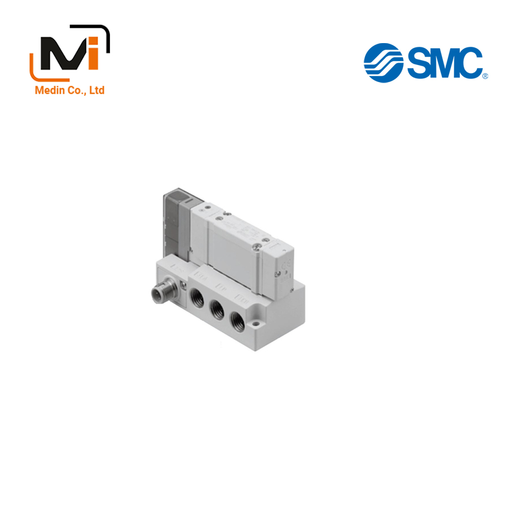
5-Port Solenoid Valve, Plug-In, SY3000/5000/7000 Series, Single Unit / Sub-Plate Type
Solenoid valve equipped with a 4-position, dual 3-port valve.
Download
Van Điện Từ SMC SY3000/5000/7000 Series SY3A00 SY3100 SY5A00 SY7A00 SY7B00 SY7C00 SY7100
5-Port Solenoid Valve, Plug-In, SY3000/5000/7000 Series Specifications – Van Điện Từ SMC
[Features] · Protective enclosure conforms to IP67 standard.· M12 waterproof connector type for easy attachment, detachment and wiring.
· Supports side, top and bottom piping. (Ports 4A, 2B)
· Power consumption has been reduced to 1/3rd of standards by decreasing wasted holding power.
· Prevents actuator and air-operated valve malfunctions caused by exhaust from other valves.
· Includes mechanism for 3-position closed center valve residual pressure release.
· Individual replacement of solenoid valves is possible without cutting off main pressure.
SY3000 Specifications
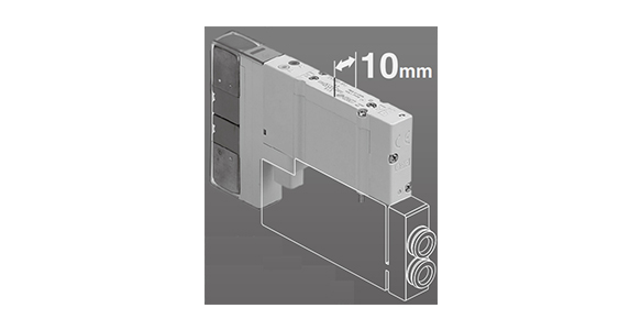
SY3000 Specifications
Can be connected to ø2 (diameter 2 mm) ø3.2 (diameter 3.2 mm), ø4 (diameter 4 mm), ø6 (diameter 6 mm) and ø8 (diameter 8 mm) fittings
- *M10/M11 type manifolds
SY5000 specifications
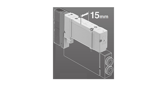
SY5000 specifications
Can be connected to ø4 (diameter 4 mm), ø6 (diameter 6 mm) and ø8 (diameter 8 mm) fittings
SY7000 specifications
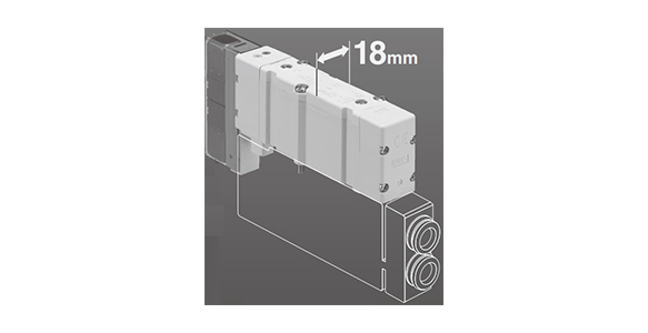
SY7000 specifications
Can be connected to ø6 (diameter 6 mm), ø8 (diameter 8 mm), ø10 (diameter 10 mm) and ø12 (diameter 12 mm) fittings
Valve Specifications
| Valve Construction | Rubber Seal | Metal Seal | ||
|---|---|---|---|---|
| Usable Fluids | Air | |||
| Internal pilot operating pressure range MPa | 2-position single | 0.15 to 0.7 | 0.1 to 0.7 (High pressure: 0.1 to 1) | |
| 2-position double | 0.1 to 0.7 | |||
| 3 Position | 0.2 to 0.7 | |||
| 4-position, dual 3-port valve | 0.15 to 0.7 | – | ||
| External pilot operating pressure range MPa | Operating Pressure Range | -100 kPa to 0.7 (4-position: -100 kPa to 0.6) | -100 kPa to 0.7 (High pressure: -100 kPa to 1) | |
| Pilot Pressure Range | 2-position single | 0.25 to 0.7 | 0.1 to 0.7 (High pressure: 0.1 to 1) | |
| 2-position double | ||||
| 3 Position | ||||
| 4-position, dual 3-port valve | Operating pressure +0.1 or more (min. 0.25) to 0.7 | – | ||
| Ambient Temperature and Operating Fluid Temperature °C | -10 to 50 (no freezing) | |||
| Maximum Operating Frequency Hz | SY3000 SY5000 |
2 Position Single, Double | 5 | 20*1 |
| 4-position, dual 3-port valve | ||||
| 3 Position | 3 | 10*1 | ||
| SY7000 | 2 Position Single, Double | 5 | 10*1 | |
| 4-position, dual 3-port valve | 3 | – | ||
| 3 Position | 3 | 10*1 | ||
| Manual | Non-locking, push type | |||
| Push-turn locking slotted type | ||||
| Push-turn locking hand-operated type | ||||
| Sliding lock type | ||||
| Pilot Exhaust Method | Internal Pilot | Main valve, pilot valve common exhaust type | Main valve, pilot valve individual exhaust type | |
| External Pilot | Pilot valve individual exhaust type | |||
| Lubrication | Not required | |||
| Mounting orientation*2 | Free | Single: free Double / 3-position: Main valve shall be horizontal |
||
| Impact resistance/Vibration resistance*2 (m/s2) | 150/30 | |||
| Enclosure | IP67 (Based on IEC60529)* | |||
| Coil rated voltage (DC) | 24, 12 V | |||
| Allowable voltage fluctuation (V) | ±10% of rated voltage*3 | |||
| Power Consumption W | Standard | 0.35 (with light: 0.4) | ||
| High-pressure, quick response | 0.9 (with light: 0.95) | |||
| With power saving circuit | Standard: 0.1*4(With indicator light only) [Inrush 0.4, Holding 0.1], High-pressure: 0.4*4(With indicator light only) [Inrush 0.95, Holding 0.4] |
|||
| Surge Voltage Suppressor | Diode (varistor for non-polar type) | |||
| Indicator Light | LED | |||
- *As there are limitations to the operating environment of the metal seal, see precautions specific to the product.
*1: Use at 5 Hz or less with the energy saving circuit.
*2: Impact resistance: No malfunctions after testing under the following conditions: in the axial direction and at a right angle to the main valve and armature in both energized and non-energized states (once for each condition state). (Initial value)
Vibration resistance: No malfunctions occurred in a 1-sweep test between 45 and 2,000 Hz. The test was performed in both energized and non-energized states and in the axial direction and at right angles to the main valve and armature. (Initial value)
See applicable pages in the manufacturer’s catalog for information regarding how to secure manifolds for the DIN rail mounted type.
*3: S, Z and T types (with energy saving circuit) may experience voltage drops caused by internal circuits. Use within the allowable voltage fluctuation range below.
- S and Z type: 24 V DC: -7% to +10%, 12 V DC: -4% to +10%
- T type: 24 V DC: -8% to +10%, 12 V DC: -6% to +10%
*4: See applicable pages in the manufacturer’s catalog for details.
SY3A00-5U1-W3-01F
SY3A00-5U1-W7-01
SY3A00-5U1-WO-01
SY3A00-5U1-WO-01F
SY3A00-5U1-WO-01N
SY3A00-5UD1-W1-01
SY3A00-5UD1-W3-01
SY3A00-5UE1-W1-01
SY3A00-5Z1-W1-01
SY3A00-5Z1-W2-01
SY3A00-5Z1-WO-01
SY3A00-5ZD1-W1-01
SY3A00-5ZD1-W7-01
SY3A00-51-W1-01
SY3A00-51-W3-01
SY3A00B-5U1-W1-01
SY3A00B-5U1-W1-01N
SY3A00B-5U1-W7-B01N
SY3A00H-5UE1-W3-01F
SY3A00HT-5Z1-W1-01
SY3A30-5U1-C4-W1-V01T
SY3A30-5Z1-C6-W2-01
SY3A30-51-C6-W1-V01
SY3A30HT-5Z1-C4-W3-V01
SY3A30R-5UF1-C6-B-W1-V01
SY3B00R-5Z1-WO-01
SY3B30R-5UF1-C6-B-W1-V01
SY3C00-5U1-WO-01F
SY3C00B-5U1-WO-01
SY3C00RT-5NZ1-W1-01
SY3C00RT-5Z1-W1-01
SY3C00T-5ZD1-W2-01N
SY3100-5D1-B-W4-01
SY3100-5D1-W4-01
SY3100-5E1-W1-01
SY3100-5E1-W2-B01
SY3100-5NZ1-H-W2-01
SY3100-5NZ1-H-WO-01
SY3100-5NZ1-W1-01
SY3100-5NZ1-W1-01N
SY3100-5NZ1-W2-01
SY3100-5NZ1-W7-01
SY3100-5NZ1-WO-01
SY5A00-5U1-K-W7-02F
SY5A00-5U1-W1-02
SY5A00-5U1-W3-02
SY5A00-5U1-W3-B02N
SY5A00-5U1-W4-02
SY5A00-5U1-W7-02
SY5A00-5U1-W7-02F
SY5A00-5U1-W7-02N
SY5A00-5U1-WO-02
SY5A00-5U1-WO-02F
SY5A00-5U1-WO-02N
SY5A00-5U1-WO-02T
SY5A00-5UD1-W1-02
SY5A00-5UD1-W3-02
SY5A00-5UD1-WO-02F
SY5A00-5UF1-K-W7-02F
SY5A00-5UF1-W1-02
SY5A00-5Z1-W1-02
SY5A00-51-W3-B02
SY5A00-51-W7-02
SY5A00B-51-WO-02
SY5A00R-5U1-W1-02
SY5A00RB-5U1-W2-02
SY7A00-5U1-W7-03
SY7A00-5U1-WO-03
SY7A00-5U1-WO-03F
SY7A00-5UD1-WO-03F
SY7A00-5UF1-W4-03F
SY7A00R-5U1-W7-03
SY7A00R-51-WO-03
SY7A00RB-5U1-W2-03
SY7A00T-5NZ1-W4-03
SY7B00-61-W1-03
SY7C00-5UF1-W2-03
SY7100-5NZ1-H-W7-03
SY7100-5NZ1-WO-03
SY7100-5U1-B-W7-03
SY7100-5U1-W1-03
SY7100-5U1-W1-03T
SY7100-5U1-W2-03
SY7100-5U1-W2-03T
SY7100-5U1-W3-03
SY7100-5U1-W4-03
SY7100-5U1-W4-03T
SY7100-5U1-W7-03
SY7100-5U1-W7-03N
SY7100-5U1-W7-03T
SY7100-5U1-WO-03
SY7100-5U1-WO-03F
Giới thiệu SMC Việt Nam
SMC là thương hiệu hàng đầu thế giới trong lĩnh vực công nghệ khí nén, cung cấp các giải pháp tiên tiến nhằm hỗ trợ tự động hóa và tối ưu hóa quy trình sản xuất.
Với nền tảng vững chắc trong ngành, SMC Việt Nam luôn đi đầu trong việc nghiên cứu, đổi mới và phát triển sản phẩm, góp phần nâng cao năng suất và tiết kiệm lao động cho các doanh nghiệp công nghiệp.
Với phương châm “đóng góp vào tự động hóa và tiết kiệm lao động trong ngành công nghiệp”, SMC Việt Nam không ngừng cải tiến và mang đến những sản phẩm công nghệ tiên tiến nhất.
SMC Việt Nam cam kết cung cấp những giải pháp hiện đại, giúp khách hàng duy trì lợi thế cạnh tranh trên thị trường.
Medin Company cung cấp các sản phẩm SMC tại Việt Nam.
Đa dạng các sản phẩm và giải pháp khí nén phục vụ cho nhiều ngành công nghiệp khác nhau, bao gồm:
- Xy lanh khí nén – Giúp kiểm soát chuyển động chính xác và hiệu quả.
- Van điện từ – Ứng dụng rộng rãi trong điều khiển luồng khí nén.
- Bộ lọc khí nén – Đảm bảo chất lượng khí nén tối ưu.
- Cảm biến và bộ điều khiển – Tăng cường tự động hóa trong quy trình sản xuất.
———————-
👉 Xem thêm sản phẩm của SMC
Liên Hệ Medin Co., Ltd
- Công ty TNHH Mễ Đình được thành lập từ năm 2006.
- Từ đó đến nay Medin luôn là Công ty dẫn đầu về lĩnh vực Tự Động Hoá ở thị trường trong và ngoài nước với hơn 1,000 khách hàng, cùng với rất nhiều dự án lớn nhỏ cho các nhà máy sản xuất.
- Chúng tôi cung cấp cho khách hàng những giải phát tuyệt vời nhất trong việc ứng dụng Tự Động Hoá vào sản xuất
- Phương châm: “Giải pháp của chúng tôi, lợi ích của khách hàng”
- Giá trị cốt lõi: “Uy tín là sự tồn tại của chúng tôi”

- Hơn 20 năm kinh nghiệm, chúng tôi có đội ngũ kỹ sư nhiều kinh nghiệm, có khả năng tư vấn, đưa ra giải pháp có lợi nhất cho khách hàng.
- Sự tin tưởng và đồng hành của khách hàng là động lực để Medin phát triển cao hơn và xa hơn.

