Van Điện Từ SMC V100 Series V114 V124 V124A V124T
3-Port Solenoid Valve, Direct Operated, Rubber Seal, V100 Series
A solenoid valve that is effective in preventing short-circuit accidents caused by foreign objects entering the connector.
Download
Van Điện Từ SMC V100 Series V114 V124 V124A V124T
3-Port Solenoid Valve, Direct Operated, Rubber Seal, V100 Series Specifications – Van Điện Từ SMC
[Features] ・ Power consumption: 0.1 W (With power saving circuit)・ Connector with protective cover with dust-proof measures Ass’y
・ The cover is made of chloroprene rubber for electricity, which has excellent weather resistance and electrical insulation
(Do not allow it to get wet with cutting oil, etc. )
・ Clean external appearance due to the use of round cord [10-Series, Clean Series] ・ It is suitable for clean environment
· It prevents dust generation in the cleanroom
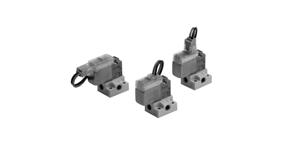
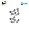
3-Port Solenoid Valve, Direct Operated, Rubber Seal, V100 Series external appearance

V114 (A) and V124 (A) JIS symbols
| Fluid | Air |
|---|---|
| Ambient Temperature and Operating Fluid Temperature °C | -10 to +50 (no freezing) |
| *1Response Time (for DC) ms | ON: 5 or less, OFF: 4 or less |
| Maximum Operating Frequency Hz | 20 |
| Manual Operation | Non-locking push type, locking type screwdriver operated type (slotted) |
| Lubrication | Not required |
| Mounting Position | Free |
| *2: Impact Resistance / Vibration Resistance: m/s2 | 150/30 |
| Enclosure | Dust-proof |
*1: Based on JIS B 8419:2010 dynamic performance test. (Standard type: coil temperature of 20°C, at rated voltage, with no surge voltage suppressor)
*2: Impact resistance: No malfunctions after testing using an impact tester under the following conditions: in the axial direction and at a right angle to the armature in both energized and non-energized states (once for each condition state). (Initial value)
Vibration resistance: No malfunctions occurred in a 1-sweep test between 45 and 2,000 Hz. The test was performed in both energized and non-energized states and in the axial direction and at a right angle to the armature. (Initial value)
Solenoid Specifications
| Series | V114/V124 | V114A/V124A | ||
|---|---|---|---|---|
| Electrical Entry | Grommet (G) / (H), L-shaped plug connector (L), M-shaped plug connector (M) | |||
| Coil rated voltage (V) | DC | 24, 12, 6, 5, 3 | ||
| AC 50/60 Hz | 100, 110, 200, 220 | – | ||
| Allowable Voltage Fluctuation | -10 to +10%* | |||
| Power Consumption W | DC | Standard: 0.35 (with light: 0.4), with energy-saving circuit: 0.1 *[startup: 0.4, holding: 0.1] | 1 W (with light: 1.1) | |
| Apparent Power VA | AC | 100 V | 0.78 (with light: 0.81) | – |
| 110 V [115 V] | 0.86 (with light: 0.89) [0.94 (with light: 0.97)] | – | ||
| 200 V | 1.18 (with light: 1.22) | – | ||
| 220 V [230 V] | 1.30 (with light: 1.34) [1.42 (with light: 1.46)] | – | ||
| Surge Voltage Suppressor | See the SMC catalog. | |||
| Indicator Light | LED | |||
- The 110‑V AC and 115‑V AC types are interchangeable. The 220‑V AC and 230‑V AC types are also interchangeable.
- For 115 V AC and 230 V AC, the allowable voltage fluctuation is -15 to +5% of the rated voltage.
- As the S, Z, and T types (with power saving circuit) have voltage drop due to the internal circuits, the allowable voltage fluctuation should be within the range given below.
S, Z type 24 V DC: -7% to +10%
12 V DC: -4% to +10%, T type 24 V DC: -8% to +10%
12 V DC: -6% to +10% - *If the valve is continuously energized for long periods, use an energy-saving type or DC specification.
*Refer to the SMC catalog for details.
Model
| Valve Model Numbers | Switching Method | Type | Operating Pressure Range *4 (MPa) |
When Using in Vacuum (MPa) *4 | Piping connection port diameter | Weight (g) *2 | |||
|---|---|---|---|---|---|---|---|---|---|
| Port 1 | 3-Port | Port 1, Port 3 | 2 port | Grommet Type | L Type, M Type | ||||
| V114 | N.C. | Standard | 0 to 0.7 | -100 kPa to 0.6 | -100 kPa to 0 | M5 × 0.8 | M5 × 0.8 | V1□4: 13 (27) V1□4A: 16 (30) |
Plug connector V1□4: 12 (26) V1□4A: 16 (29) |
| V114A | N.C. | High flow rate | 0 to 0.7 | -100 kPa to 0.6 | -100 kPa to 0 | M5 × 0.8 | M5 × 0.8 | ||
| V124*1 | N.C. | Standard | 0 to 0.7 | -100 kPa to 0 | -100 kPa to 0.6 | M5 × 0.8 | M5 × 0.8 | ||
| V124A*1 | N.C. | High flow rate | 0 to 0.7 | -100 kPa to 0 | -100 kPa to 0.6 | M5 × 0.8 | M5 × 0.8 | ||
| Valve Model Numbers | Flow Rate Characteristics | |||||
|---|---|---|---|---|---|---|
| 1 → 2 [3 → 2 *3] | 2 → 3 [2 → 1 *3] | |||||
| C [dm3/(s·bar)] | b | Cv | C [dm3/(s·bar)] | b | Cv | |
| V114 | 0.037 | 0.11 | 0.008 | 0.054 | 0.35 | 0.015 |
| V114A | 0.076 | 0.07 | 0.016 | 0.099 | 0.23 | 0.024 |
| V124*1 | 0.054 | 0.35 | 0.015 | 0.037 | 0.11 | 0.008 |
| V124A*1 | 0.099 | 0.23 | 0.024 | 0.076 | 0.07 | 0.016 |
*1: For V124 and V124A, apply pressure from port 3 and exhaust from port 1.
*2: Values in ( ) are with the subplate.
*3: For 10-V124 (A).
*4: When the difference between the primary and secondary sides is extremely small (guideline is 0.001 MPa or less), the quality of the air and lubricant oil in the solenoid valve (condensate mixture, etc.) may prevent air from being output or may cause the flow rate to dramatically decrease.
V114-1GZ-M5
V114-1M
V114-1M-M5
V114-1MOU
V114-1MOU-M5
V114-1MOZ
V114-2G-M5
V114-2MZ-M5
V114-5G
V114-5G-M5
V114-5GS
V114-5GZ
V114-5HU
V114-5HU-M5
V124-5G
V124-5G-M5
V124-5GR
V124-5GZ
V124-5HS-M5
V124-5HZ
V124-5LO-M5
V124-5LOU
V124-5M-M5
V124-5MU-M5
V124-5MZ-M5
V114-1G-M5
V114-1GB
V114-1GZ
V114-1GZ-M5
V114-1GZB-M5
V114-1H-M5
V114-1HZ
V114-1HZ-M5
V114-1L
V114-1L-M5
V114-1LN
V114-1LO
V114-1LOZ
V114-1LOZ-M5
V114-1LOZB
V114-1LZ
V114-1LZ-M5
V114-1LZB
V114-1LZB-M5
V114-4L-M5
V114A-5LB-M5
V114A-6LB
V114A-VG
V124-3LZ-M5
V124-5MP
V124-5MP-M5
V124-5MPZ
V124-5MPZ-M5
V124-SMZ-M5
V124A-6M
V124A-6M-M5
V124T-5LZB
V114-1LZB-M5
V114-1M
V114-1M-M5
V114-1MB
V114-1MOZ
V114-1MZ
V114-1MZ-M5
V114-1MZB-M5
V114-2G
V114-2G-M5
V124A-5MUB-M5
V124A-6MU-M5
V124A-RG-M5
V124T-5GZ-M5
V124T-5LOZ
V124T-5LOZB
V124T-5LZ
V124T-5MZ
V124T-5MZ-M5
V124T-6MZ-M5
V114-5LZB-M5
V114-5M
V114-5M-M5
V114-5MNZB
V114-5MOU
V114-5MOU-M5
V114-5MOZ-M5
V114-5MOZB
V114-5MS-M5
V114-5MU
V114-5MU-M5
V114-5MZ
V114-5MZ-M5
Giới thiệu SMC Việt Nam
SMC là thương hiệu hàng đầu thế giới trong lĩnh vực công nghệ khí nén, cung cấp các giải pháp tiên tiến nhằm hỗ trợ tự động hóa và tối ưu hóa quy trình sản xuất.
Với nền tảng vững chắc trong ngành, SMC Việt Nam luôn đi đầu trong việc nghiên cứu, đổi mới và phát triển sản phẩm, góp phần nâng cao năng suất và tiết kiệm lao động cho các doanh nghiệp công nghiệp.
Với phương châm “đóng góp vào tự động hóa và tiết kiệm lao động trong ngành công nghiệp”, SMC Việt Nam không ngừng cải tiến và mang đến những sản phẩm công nghệ tiên tiến nhất.
SMC Việt Nam cam kết cung cấp những giải pháp hiện đại, giúp khách hàng duy trì lợi thế cạnh tranh trên thị trường.
Medin Company cung cấp các sản phẩm SMC tại Việt Nam.
Đa dạng các sản phẩm và giải pháp khí nén phục vụ cho nhiều ngành công nghiệp khác nhau, bao gồm:
- Xy lanh khí nén – Giúp kiểm soát chuyển động chính xác và hiệu quả.
- Van điện từ – Ứng dụng rộng rãi trong điều khiển luồng khí nén.
- Bộ lọc khí nén – Đảm bảo chất lượng khí nén tối ưu.
- Cảm biến và bộ điều khiển – Tăng cường tự động hóa trong quy trình sản xuất.
———————-
👉 Xem thêm sản phẩm của SMC
Liên Hệ Medin Co., Ltd
- Công ty TNHH Mễ Đình được thành lập từ năm 2006.
- Từ đó đến nay Medin luôn là Công ty dẫn đầu về lĩnh vực Tự Động Hoá ở thị trường trong và ngoài nước với hơn 1,000 khách hàng, cùng với rất nhiều dự án lớn nhỏ cho các nhà máy sản xuất.
- Chúng tôi cung cấp cho khách hàng những giải phát tuyệt vời nhất trong việc ứng dụng Tự Động Hoá vào sản xuất
- Phương châm: “Giải pháp của chúng tôi, lợi ích của khách hàng”
- Giá trị cốt lõi: “Uy tín là sự tồn tại của chúng tôi”

- Hơn 20 năm kinh nghiệm, chúng tôi có đội ngũ kỹ sư nhiều kinh nghiệm, có khả năng tư vấn, đưa ra giải pháp có lợi nhất cho khách hàng.
- Sự tin tưởng và đồng hành của khách hàng là động lực để Medin phát triển cao hơn và xa hơn.


