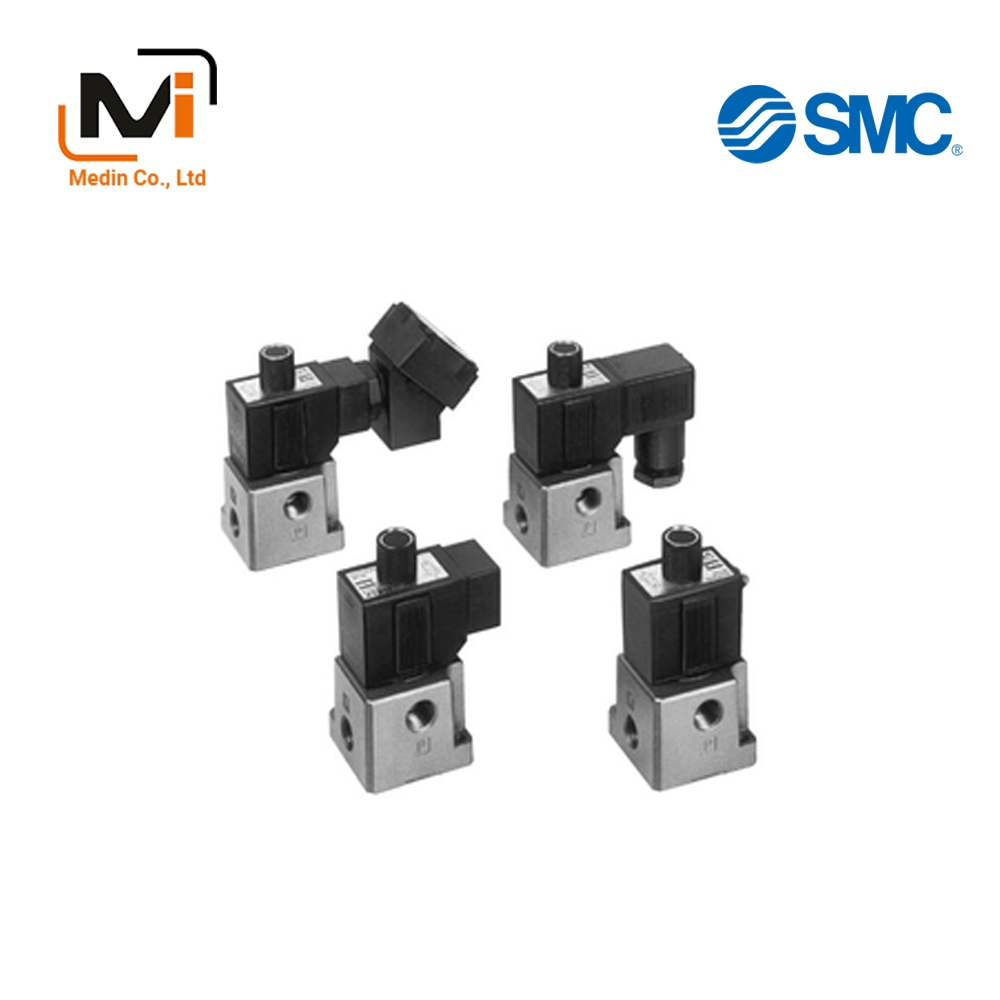
Van Điện Từ SMC Solenoid Valve VT317 Series VO317 VT317
3‑Port Solenoid Valve Direct Operated Poppet Type VT317 Series
Download
Van Điện Từ SMC Solenoid Valve VT317 Series VO317 VT317
3-Port Solenoid Valve, Direct Operated Poppet Type, Rubber Seal, VT317 Series Specifications- Van Điện Từ SMC
[Features] · Compact yet with a large valve capacity· Suitable for use in vacuum applications
· 6 valve functions in 1 valve
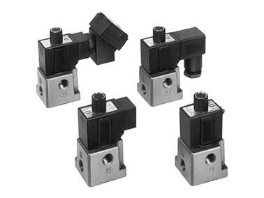
VT317 Series, rubber seal external appearance
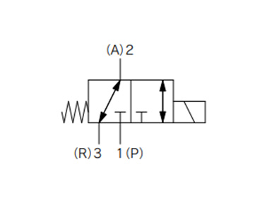
VT317 Series Rubber Seal JIS symbol
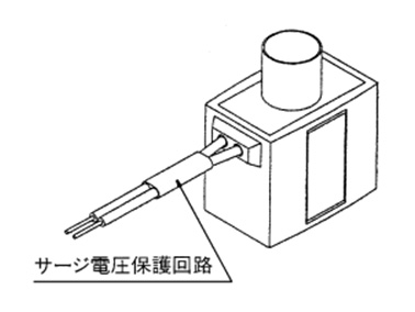
Surge voltage suppressor mounting part (for G)
| Switching Method | Direct operation type 2-position single solenoid | ||
|---|---|---|---|
| Usable Fluids | Air | ||
| Operating Pressure Range | 0 to 0.9 MPa | ||
| Ambient Temperature and Operating Fluid Temperature | -10 to +50°C (no freezing.) | ||
| Response time*1 | 30 ms or less (at 0.5 MPa) | ||
| Maximum Operating Frequency | 10 Hz | ||
| Lubrication | Not required (Use turbine oil class 1 ISO VG32, if lubricated) | ||
| Manual Operation | Non-locking, push type | ||
| Mounting Orientation | Free | ||
| Impact resistance / Vibration resistance*2 | 150/50 m/s2 | ||
| Enclosure | Dust-proof | ||
| Electrical Entry | Grommet, conduit Conduit terminal, DIN terminal |
||
| Coil rated voltage (V) | AC (50/60 Hz) | 100, 200, 110, 220, 240 | |
| DC | 24, 12 | ||
| Allowable Voltage Fluctuation | -15% to +10% of rated voltage | ||
| Apparent power*3 | AC | Starting | 19 VA (50 Hz), 16 VA (60 Hz) |
| Holding | 11 VA (50 Hz), 7 VA (60 Hz) | ||
| Power consumption*3 | DC | Without indicator light: 6 W, With indicator light: 6.3 W | |
| Light and Surge Voltage Suppressor (Not available for the grommet type.) |
AC | Varistor, neon bulb | |
| DC | Varistor, LED: 100 V or more is neon bulb | ||
*1: Based on JIS B 8419:2010 dynamic performance test. (Coil temperature of 20°C, at rated voltage, with no surge voltage suppressor)
*2: Impact resistance: No malfunctions after testing using a drop-type impact tester under the following conditions: in the axial direction and at a right angle to the main valve and armature in both energized and non-energized states (once for each condition state). (Initial value)
Vibration resistance: No malfunction occurred in 1 sweep test between 45 and 1,000 Hz. The test was performed in both energized and de-energized states in the axial and right angle directions of the main valve/armature. (Initial value)
*3: When rated voltage is applied.
Flow Rate Characteristics / Weight Table
| Valve type | Flow Rate Characteristics | Weight | |||||||||||
|---|---|---|---|---|---|---|---|---|---|---|---|---|---|
| 1→2 (P→A) | 2→3 (A→R) | 3→2 (R→A) | 2→1 (A→P) | ||||||||||
| C (dm3/(s·bar)) |
b | Cv | C (dm3/(s·bar)) |
b | Cv | C (dm3/(s·bar)) |
b | Cv | C (dm3/(s·bar)) |
b | Cv | Grommet | |
| VT317 | 2.4 | 0.26 | 0.62 | 2.6 | 0.34 | 0.67 | 2.8 | 0.25 | 0.67 | 2.5 | 0.37 | 0.66 | 0.29 kg |
| VT317V (Vacuum specification) |
|||||||||||||
| VT317E (Continuous duty type) |
|||||||||||||
*Value for valve single unit. This will differ for the manifold. See manifold specifications in the manufacturer’s catalog for details.
VO317-1CS
VO317-1D
VO317-1D-Q
VO317-1DS
VO317-1DS-Q
VO317-1DZ
VO317-1DZ-Q
VO317-1G
VO317-1GS
VO317-1H
VO317-1HS
VO317-1T
VO317-1TS
VO317-1TZ
VO317-2C
VO317-2CS
VO317-2D
VO317-2D-Q
VO317-2DS
VO317-2DZ
VO317-3D-Q
VO317-3DZ
VO317-3DZ-Q
VO317-3G
VO317-3GS
VO317-3HS
VO317-3T
VO317-3TZ
VO317-4D
VO317-4D-Q
VO317-4DS
VO317-4DZ
VO317-4DZ-Q
VO317-4G
VO317-4GS
VO317-4H
VO317-4HS
VO317-4T
VO317-4TZ
VT317-1C-02N
VT317-1CS-02
VT317-1D-02
VT317-1D-02-Q
VT317-1D-02F
VT317-1D-02F-Q
VT317-1D-02N
VT317-1D-02T
VT317-1DS-02
VT317-1DS-02-Q
VT317-1DS-02F
VT317-1DZ-02
VT317-1DZ-02-Q
VT317-1DZ-02F
VT317-1DZ-02F-Q
VT317-1DZ-02N
VT317-1G-02
VT317-1G-02F
VT317-1G-02N
VT317-1G-02T
VT317-1GS-02
VT317-1GS-02F
VT317-1GS-02N
VT317-1T-02F
VT317-1T-02N
VT317-1TS-02
VT317-1TZ-02
VT317-1TZ-02F
VT317-1TZ-02N
VT317-2C-02
VT317-2CS-02
VT317-2D-02
VT317-2D-02-Q
VT317-2D-02F
VT317-2D-02F-Q
VT317-2D-02N
VT317-2DS-02
VT317-2DZ-02
VT317-2DZ-02-Q
VT317-2DZ-02F
VT317-2DZ-02N
VT317-2G-02
VT317-2G-02F
Giới thiệu SMC Việt Nam
SMC là thương hiệu hàng đầu thế giới trong lĩnh vực công nghệ khí nén, cung cấp các giải pháp tiên tiến nhằm hỗ trợ tự động hóa và tối ưu hóa quy trình sản xuất.
Với nền tảng vững chắc trong ngành, SMC Việt Nam luôn đi đầu trong việc nghiên cứu, đổi mới và phát triển sản phẩm, góp phần nâng cao năng suất và tiết kiệm lao động cho các doanh nghiệp công nghiệp.
Với phương châm “đóng góp vào tự động hóa và tiết kiệm lao động trong ngành công nghiệp”, SMC Việt Nam không ngừng cải tiến và mang đến những sản phẩm công nghệ tiên tiến nhất.
SMC Việt Nam cam kết cung cấp những giải pháp hiện đại, giúp khách hàng duy trì lợi thế cạnh tranh trên thị trường.
Medin Company cung cấp các sản phẩm SMC tại Việt Nam.
Đa dạng các sản phẩm và giải pháp khí nén phục vụ cho nhiều ngành công nghiệp khác nhau, bao gồm:
- Xy lanh khí nén – Giúp kiểm soát chuyển động chính xác và hiệu quả.
- Van điện từ – Ứng dụng rộng rãi trong điều khiển luồng khí nén.
- Bộ lọc khí nén – Đảm bảo chất lượng khí nén tối ưu.
- Cảm biến và bộ điều khiển – Tăng cường tự động hóa trong quy trình sản xuất.
———————-
👉 Xem thêm sản phẩm của SMC
Liên Hệ Medin Co., Ltd
- Công ty TNHH Mễ Đình được thành lập từ năm 2006.
- Từ đó đến nay Medin luôn là Công ty dẫn đầu về lĩnh vực Tự Động Hoá ở thị trường trong và ngoài nước với hơn 1,000 khách hàng, cùng với rất nhiều dự án lớn nhỏ cho các nhà máy sản xuất.
- Chúng tôi cung cấp cho khách hàng những giải phát tuyệt vời nhất trong việc ứng dụng Tự Động Hoá vào sản xuất
- Phương châm: “Giải pháp của chúng tôi, lợi ích của khách hàng”
- Giá trị cốt lõi: “Uy tín là sự tồn tại của chúng tôi”

- Hơn 20 năm kinh nghiệm, chúng tôi có đội ngũ kỹ sư nhiều kinh nghiệm, có khả năng tư vấn, đưa ra giải pháp có lợi nhất cho khách hàng.
- Sự tin tưởng và đồng hành của khách hàng là động lực để Medin phát triển cao hơn và xa hơn.
