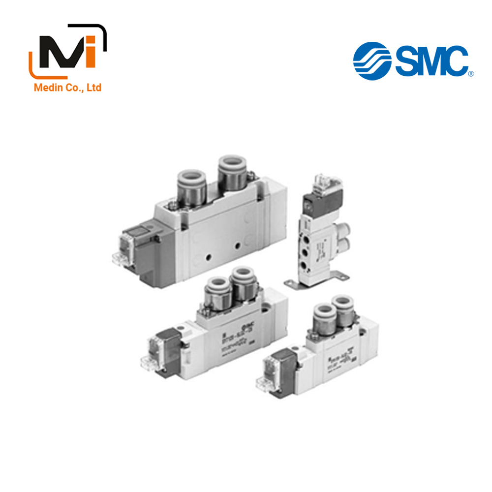
Van Điện Từ SMC Solenoid Valve SY7000 Series SY7120 SY7220 SY7320 SY7420 SY7520
5-Port Solenoid Valve Body Ported Single Unit SY7000 Series
[Features]
· Power consumption: 0.1 W (with power saving circuit)
Download
Van Điện Từ SMC Solenoid Valve SY7000 Series SY7120 SY7220 SY7320 SY7420 SY7520
5-Port Solenoid Valve, Body Ported Single Unit, SY7000 Series Specifications – Van Điện Từ SMC
| Series | SY7000 | |
|---|---|---|
| Usable Fluids | Air | |
| Internal Pilot Operating Pressure Range MPa |
2-position single | 0.15 to 0.7 |
| 2-position double | 0.1 to 0.7 | |
| 3 Position | 0.2 to 0.7 | |
| Ambient and fluid temperature (°C) | -10 to 50 (no freezing) | |
| Maximum operating frequency (Hz) | 2 Position Single, Double | 5 |
| 3 Position | 3 | |
| Manual Operation | Non-locking push type, push-turn locking type screwdriver-operated type, push-turn locking manual-operation type | |
| Pilot Exhaust Method | Main valve, pilot valve common exhaust type | |
| Lubrication | Not required | |
| Mounting Orientation | Free | |
| *Impact resistance/Vibration-resistance (m/s2) | 150/30 | |
| Enclosure | Dust-proof (*DIN terminal and M8 connector are IP65) | |
*Based on IEC60529.
*Impact resistance: No malfunctions after testing under the following conditions: in the axial direction and at a right angle to the main valve and armature in both energized and non-energized states (once for each condition state). (Initial value)
Vibration resistance: No malfunctions occurred in a 1-sweep test between 45 and 2,000 Hz. The test was performed in both energized and non-energized states and in the axial direction and at right angles to the main valve and armature. (Initial value)
Solenoid Specifications
| Electrical Entry | Grommet (G) (H) DIN terminal (D) (Y) L-type plug connector (L) M8 connector (W) M-type plug connector (M) |
|||
|---|---|---|---|---|
| G, H, L, M, W | D, Y | |||
| Coil rated voltage (V) | DC | 24, 12, 6, 5, 3 | 24, 12 | |
| AC 50/60 Hz | 100, 110, 200, 220 | |||
| Allowable Voltage Fluctuation | ±10% of rated voltage* | |||
| Power Consumption W | DC | Standard | 0.35 (with light: 0.4) [0.94 (with DIN terminal light: 0.45)] | |
| With power saving circuit | 0.1 (only with light) * [Startup 0.4, holding 0.1] |
|||
| *Apparent power (VA) | AC | 100 V | 0.78 (with light: 0.81) | 0.78 (with light: 0.87) |
| 110 V 115 V |
0.86 (with light: 0.89) [0.94 (with indicator light: 0.97)] |
0.86 (with light: 0.97) [0.94 (with light: 1.07)] |
||
| 200 V | 1.18 (with light: 1.22) | 1.15 (with light: 1.30) | ||
| 220 V [230 V] |
1.30 (with light: 1.34) [1.42 (with light: 1.46)] |
1.27 (with light: 1.46) [1.39 (with light: 1.60)] |
||
| Surge Voltage Suppressor | Diode (varistor for DIN terminal and non-polar type are ) | |||
| Indicator Light | LED (neon bulb for DIN terminal AC) | |||
- *The 110 V AC and 115 V AC types are interchangeable. The 220 V AC and 230 V AC types are also interchangeable.
- For 115 V AC and 230 V AC, the allowable voltage fluctuation is -15 to +5% of the rated voltage.
- *Energy-saving circuit not available with DIN terminal / M8 connector.
- For details, see the SMC catalog.
Response Time
*Standard type based on JIS B8419:2010 dynamic performance testing (Coil temperature 20°C, at rated voltage)
| Switching Method | Response Time ms (at 0.5 MPa) | ||
|---|---|---|---|
| Without light or surge voltage suppressor | With light and surge voltage suppressor | ||
| S, Z type | R, U type | ||
| 2-position single | 31 or less | 38 or less | 33 or less |
| 2-position double | 27 or less | 30 or less | 28 or less |
| 3 Position | 50 or less | 56 or less | 50 or less |
Flow Rate Characteristics / Weight Table
| Valve Model Numbers | Switching Method | Piping connection port diameter | Flow Rate Characteristics | Weight g | ||||||||||
|---|---|---|---|---|---|---|---|---|---|---|---|---|---|---|
| 1, 5, 3 (P, EA, EB) | 4, 2 (A, B) | 1 → 4/2 (P → A/B) | 4/2 → 5/3 (A/B → EA/EB) | Grommet | L, M plug connector | DIN terminal | W M8 connector | |||||||
| C (dm3 / [s·bar]) | b | Cv | C (dm3 / [s·bar]) | b | Cv | |||||||||
| SY7□20-□-02 | 2 Position | Single | 1 (P) port 1/4 5, 3 (EA, EB) port 1/8 |
1/4 | 4.1 | 0.23 | 0.93 | 3.3 | 0.33 | 0.81 | 101 | 104 | 125 | 108 |
| Double | 120 | 125 | 167 | 133 | ||||||||||
| 3 Position | Closed Center | 2.9 | 0.31 | 0.70 | 2.4 | 0.38 | 0.63 | 128 | 133 | 175 | 141 | |||
| Exhaust Center | 2.5 | 0.39 | 0.65 | 3.4 [2.1] |
0.35 [0.38] |
0.82 [0.54] |
||||||||
| Pressure Center | 4.3 [2.4] |
0.23 [0.32] |
0.97 [0.61] |
2.2 | 0.39 | 0.58 | ||||||||
| SY7□20-□-C8 | 2 Position | Single | C8 (ø8 [diameter 8 mm] single-action fitting) |
3.2 | 0.26 | 0.77 | 3.2 | 0.37 | 0.82 | 107 | 110 | 131 | 114 | |
| Double | 126 | 132 | 174 | 140 | ||||||||||
| 3 Position | Closed Center | 2.6 | 0.24 | 0.63 | 2.4 | 0.31 | 0.62 | 134 | 140 | 182 | 148 | |||
| Exhaust Center | 2.4 | 0.25 | 0.57 | 2.6 [1.9] |
0.42 [0.46] |
0.70 [0.56] |
||||||||
| Pressure Center | 3.3 [2.4] |
0.28 [0.22] |
0.78 [0.57] |
2.2 | 0.34 | 0.60 | ||||||||
| SY7□20-□-C10 | 2 Position | Single | C10 (ø10 (diameter 10 mm) single-action fitting) |
3.8 | 0.26 | 0.86 | 3.2 | 0.34 | 0.82 | 103 | 105 | 126 | 109 | |
| Double | 122 | 127 | 169 | 135 | ||||||||||
| 3 Position | Closed Center | 2.8 | 0.27 | 0.67 | 2.4 | 0.21 | 0.59 | 130 | 135 | 177 | 143 | |||
| Exhaust Center | 2.5 | 0.25 | 0.59 | 2.7 [2.0] |
0.38 [0.38] |
0.70 [0.56] |
||||||||
| Pressure Center | 3.8 [2.4] |
0.25 [0.31] |
0.89 [0.61] |
2.3 | 0.38 | 0.61 | ||||||||
*Values shown inside brackets are when at normal position.
SY7120-1D-02-F1
SY7120-1D-02-F2
SY7120-1D-02F-Q
SY7120-1D-02N
SY7120-1D-02N-F2
SY7120-1D-C8
SY7120-1D-C8-F1
SY7120-1D-C8-F2
SY7120-1D-C10
SY7120-1D-C10-F1
SY7120-1D-C10-F2
SY7120-1D-C10-Q
SY7120-1D-N11
SY7120-1DD-02
SY7120-1DD-02-F1
SY7120-1DD-02-F2
SY7120-1DD-C8
SY7120-1DD-C8-F1
SY7220-1D-02-F2
SY7220-1D-02-X90
SY7220-1D-02N-F2
SY7220-1D-C8
SY7220-1D-C8-F2
SY7220-1D-C8-F2-X20
SY7220-1D-C10
SY7220-1D-C10-F2
SY7220-1DD-02
SY7220-1DD-02-F2
SY7220-1DD-C8
SY7320-1D-02
SY7320-1D-02-F2
SY7320-1D-02-F2-Q
SY7320-1D-02-Q
SY7320-1D-02F
SY7320-1D-C8
SY7320-1D-C8-F2
SY7320-1D-C10
SY7320-1D-C10-F2
SY7320-1DD-02
SY7320-1DD-02-F2
SY7320-1DD-C8
SY7420-1D-02-F2
SY7420-1D-C8
SY7420-1D-C8-F2
SY7420-1D-C10
SY7420-1D-C10-F2
SY7420-1DD-02
SY7420-1DD-02-F2
SY7420-1DD-C8
SY7420-1DD-C8-F2
SY7420-1DD-C10
SY7420-1DD-C10-F2
SY7420-1DE-02
SY7420-1DE-02-F2
SY7420-1DE-C8
SY7420-1DE-C8-F2
SY7420-1DE-C10
SY7420-1DE-C10-F2
SY7420-1DO-02
SY7520-1D-02-F2
SY7520-1D-C8
SY7520-1D-C8-F2
SY7520-1D-C10
SY7520-1D-C10-F2
SY7520-1DD-02
SY7520-1DD-02-F2
SY7520-1DD-C8
SY7520-1DD-C8-F2
SY7520-1DD-C10
SY7520-1DD-C10-F2
SY7520-1DE-02
SY7520-1DE-02-F2
SY7520-1DE-C8
SY7520-1DE-C8-F2
SY7520-1DE-C10
SY7520-1DE-C10-F2
SY7520-1DO-02
SY7520-1DO-02-F2
SY7520-1DO-C8
Giới thiệu SMC Việt Nam
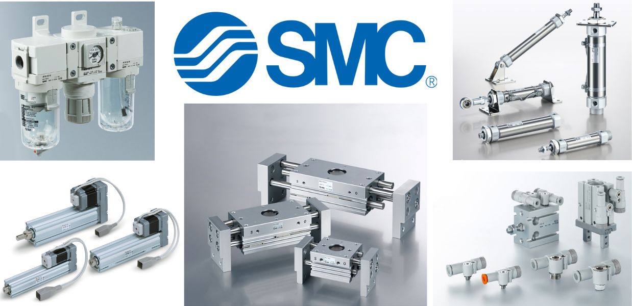
SMC là thương hiệu hàng đầu thế giới trong lĩnh vực công nghệ khí nén, cung cấp các giải pháp tiên tiến nhằm hỗ trợ tự động hóa và tối ưu hóa quy trình sản xuất.
Với nền tảng vững chắc trong ngành, SMC Việt Nam luôn đi đầu trong việc nghiên cứu, đổi mới và phát triển sản phẩm, góp phần nâng cao năng suất và tiết kiệm lao động cho các doanh nghiệp công nghiệp.
Với phương châm “đóng góp vào tự động hóa và tiết kiệm lao động trong ngành công nghiệp”, SMC Việt Nam không ngừng cải tiến và mang đến những sản phẩm công nghệ tiên tiến nhất.
SMC Việt Nam cam kết cung cấp những giải pháp hiện đại, giúp khách hàng duy trì lợi thế cạnh tranh trên thị trường.
Medin Company cung cấp các sản phẩm SMC tại Việt Nam.
Đa dạng các sản phẩm và giải pháp khí nén phục vụ cho nhiều ngành công nghiệp khác nhau, bao gồm:
- Xy lanh khí nén – Giúp kiểm soát chuyển động chính xác và hiệu quả.
- Van điện từ – Ứng dụng rộng rãi trong điều khiển luồng khí nén.
- Bộ lọc khí nén – Đảm bảo chất lượng khí nén tối ưu.
- Cảm biến và bộ điều khiển – Tăng cường tự động hóa trong quy trình sản xuất.
———————-
👉 Xem thêm sản phẩm của SMC
Liên Hệ Medin Co., Ltd
- Công ty TNHH Mễ Đình được thành lập từ năm 2006.
- Từ đó đến nay Medin luôn là Công ty dẫn đầu về lĩnh vực Tự Động Hoá ở thị trường trong và ngoài nước với hơn 1,000 khách hàng, cùng với rất nhiều dự án lớn nhỏ cho các nhà máy sản xuất.
- Chúng tôi cung cấp cho khách hàng những giải phát tuyệt vời nhất trong việc ứng dụng Tự Động Hoá vào sản xuất
- Phương châm: “Giải pháp của chúng tôi, lợi ích của khách hàng”
- Giá trị cốt lõi: “Uy tín là sự tồn tại của chúng tôi”

- Hơn 20 năm kinh nghiệm, chúng tôi có đội ngũ kỹ sư nhiều kinh nghiệm, có khả năng tư vấn, đưa ra giải pháp có lợi nhất cho khách hàng.
- Sự tin tưởng và đồng hành của khách hàng là động lực để Medin phát triển cao hơn và xa hơn.

