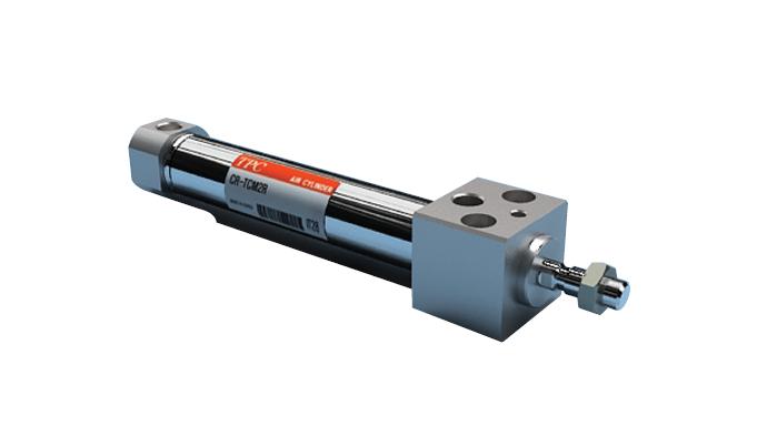
Xi Lanh Khí Nén SMC CQSKW Series CDQSKWB12 CDQSKWB16
CQSKW Series Non-Rotating Rod Type: Double Acting, Double Rod Specifications
Compact cylinder that is ideal for machine designs with small space requirements.
Download
Xi Lanh Khí Nén SMC CQSKW Series CDQSKWB12 CDQSKWB16
CQSKW Series Non-Rotating Rod Type: Double Acting, Double Rod Specifications – Xi Lanh Khí Nén SMC
[Features] · The compact auto switch (M9) will not protrude from the switch mounting groove.· Even when auto switches are used, they do not take up extra space.
· The cross-section of the cylinder tube is the same configuration with or without an auto switch.
· Square body shape that gives you flexibility for designing machines.
· Auto switch mounting direction allows for flexible design requirements.
· 2-way basic cylinder mounting.
· Non-rotating rod with high non-rotating accuracy.
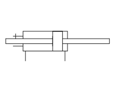
CQSKW Series symbol (without cushion)
| Tube Inner Diameter (mm) | 12 | 16 | 20 | 25 |
|---|---|---|---|---|
| Action | Double acting, double rod | |||
| Fluid | Air | |||
| Lubrication | Not required (non-lubricated) | |||
| Proof Pressure | 1.5 MPa | |||
| Maximum operating pressure | 1.0 MPa | |||
| Minimum operating pressure | 0.07 MPa | 0.05 MPa | ||
| Ambient and fluid temperature | Without auto switch: -10°C to +70 ℃ (no freezing) | |||
| With auto switch: -10°C to +60℃ (no freezing) | ||||
| Cushioning | None | |||
| Rod-end thread | Female thread | |||
| Stroke Length Tolerance | 0 to +1.0 mm | |||
| Piston Speed | 50 to 500 mm/s | |||
| Allowable kinetic energy J | 0.022 | 0.038 | 0.055 | 0.09 |
| Rod non-rotating accuracy | ±1 ° | ±0.7 ° | ||
Theoretical Output Table
(Unit: N)
| Tube inner diameter (mm) |
Rod width across flats (mm) |
Piston Area (mm2) |
Operating Pressure (MPa) | ||
|---|---|---|---|---|---|
| 0.3 | 0.5 | 0.7 | |||
| 12 | 5.2 | 90 | 27 | 45 | 63 |
| 16 | 6.2 | 168 | 50 | 84 | 117 |
| 20 | 8.2 | 256 | 77 | 128 | 179 |
| 25 | 10.2 | 401 | 120 | 200 | 281 |
Diagram
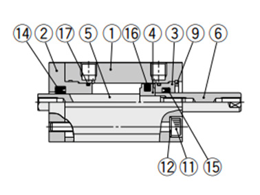
Diagram: standard, ø12 (12‑mm bore size)
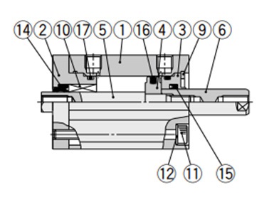
Diagram: standard, ø16 (16‑mm bore size) / ø20 (20‑mm bore size) / ø25 (25‑mm bore size)
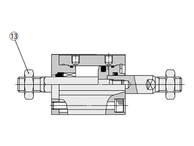
Diagram: rod end male thread
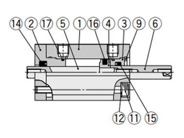
Diagram: with auto switch and built-in magnet, ø12 (12-mm bore size)
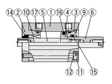
Diagram: with auto switch and built-in magnet, ø16 (16-mm bore size)
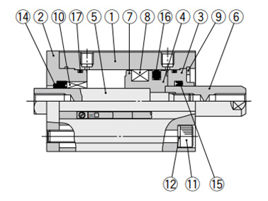
Diagram: with auto switch and built-in magnet, ø20 (20‑mm bore size) / ø25 (25‑mm bore size)
| Number | Part Name | Material | Notes |
|---|---|---|---|
| 1 | Cylinder Tube | Aluminum alloy | Hard anodized aluminum |
| 2 | Rod cover | Aluminum alloy | Anodized aluminum |
| 3 | Collar | Aluminum alloy | Anodized aluminum |
| 4 | Piston | Aluminum alloy | – |
| 5 | Piston rod A | Stainless steel | – |
| 6 | Piston rod B | Stainless steel | – |
| 7 | Spacer for Switch Type | Aluminum alloy | Chromate |
| 8 | Magnet | – | – |
| 9 | Retaining Ring | Carbon tool steel | Phosphate coated |
| 10 | Non-Rotating Guide | Oil-impregnated sintered alloy | ø16 (16‑mm bore size), ø20 (20‑mm bore size), ø25 (25‑mm bore size) |
| 11 | Hex Socket Head Cap Screw | Alloy steel | Nickel plated |
| 12 | Flat Washer | Rolled steel | Nickel plated |
| 13 | Rod end nut | Carbon steel | Zinc chromate |
| 14 | Rod seal for non-rotating | NBR | – |
| 15 | Rod packing | NBR | – |
| 16 | Piston packing | NBR | – |
| 17 | Tube gasket | NBR | – |
Drawing: ø12 to 25 (12‑mm to 25‑mm Bore Size)
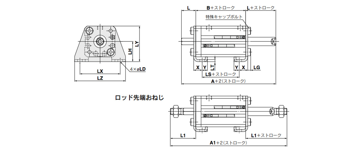
Dimensional drawings: foot type; CQSKWL, CDQSKWL
(Units: mm)
| Tube inner diameter (mm) |
Stroke range (mm) |
Without auto switch | With auto switch | L | L1 | LD | LG | LH | LT | LX | LY | LZ | X | Y | ||||||
|---|---|---|---|---|---|---|---|---|---|---|---|---|---|---|---|---|---|---|---|---|
| A | A1 | B | LS | A | A1 | B | LS | |||||||||||||
| 12 | 5 to 30 | 54 | 75 | 27 | 15 | 59 | 80 | 32 | 20 | 13.5 | 24 | 4.5 | 2.8 | 17 | 2 | 34 | 29.5 | 44 | 8 | 4.5 |
| 16 | 5 to 30 | 54 | 78 | 27 | 15 | 59 | 83 | 32 | 20 | 13.5 | 25.5 | 4.5 | 2.8 | 19 | 2 | 38 | 33.5 | 48 | 8 | 5 |
| 20 | 5 to 50 | 60 | 88 | 31 | 19 | 70 | 98 | 41 | 29 | 14.5 | 28.5 | 6.6 | 4 | 24 | 3.2 | 48 | 42 | 62 | 9.2 | 5.8 |
| 25 | 5 to 50 | 64 | 99 | 34 | 19 | 74 | 109 | 44 | 29 | 15 | 32.5 | 6.6 | 4 | 26 | 3.2 | 52 | 46 | 66 | 10.7 | 5.8 |
- Foot bracket material: carbon steel
- Surface treatment: nickel plated
Precautions
Usage Precautions
Warning
*Do not apply reverse torque to the piston rods sticking out from both sides of this cylinder at the same time. Torque makes connection threads inside loosen, which may cause an accident or malfunction.
In addition, install or remove the load with the 2 flats of the piston rod fixed on the load mounting side. At this time, be careful not to apply torque to the non-rotating guide. Do not fix the other side of the 2 flats of the piston rod and then apply reverse torque.
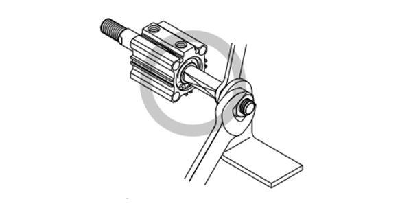
Example of correct usage of cylinder
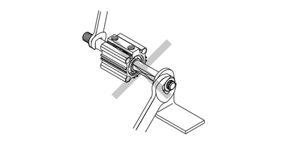
Example of incorrect use of cylinder
Caution
- *1Avoid applying rotational torque to the piston rod. The non-rotating guide may become deformed, compromising the accuracy. See below for the rotational torque allowance.
- *2The load on the piston rod must always be in an axial direction.
- ø12 (12‑mm bore size): 0.04 N·m or less
- ø16 (16‑mm bore size): 0.04 N·m or less
- ø20 (20‑mm bore size): 0.2 N·m or less
- ø25 (25‑mm bore size): 0.25 N·m or less
Installation and Removal of Retaining Rings
Caution
- *1For installation and removal, use an appropriate pair of pliers (tool for installing a type C-type retaining ring).
- *2Even when using an appropriate pair of pliers (tool for installing a type C retaining ring), proceed with caution as there is a danger of the retaining ring flying off the end of the pliers (tool) and causing bodily injury or damage to nearby equipment. After installation, make sure that the retaining ring is securely seated into the retaining ring groove before supplying air.
*See the manufacturer’s catalog for product information other than that detailed above.
Basic Information
| Cylinder Operation Method | Double Acting | Rod Operation Method | Double rod | Main Body Shape | Plate Cylinder |
|---|---|---|---|---|---|
| Additional Function | With rod detent function | Environment, Applications | Standard | End Locking | No |
| Valves | No |
CDQSKWB12-5D-M9BVL
CDQSKWB12-5D-M9BVS
CDQSKWB12-5D-M9NV
CDQSKWB12-5D-M9NVS
CDQSKWB12-5DM
CDQSKWB12-5DM-M9BVL
CDQSKWB12-5DM-M9BVLS
CDQSKWB12-5DM-M9NVLS
CDQSKWB12-10D
CDQSKWB12-10D-A93
CDQSKWB12-10D-A93L
CDQSKWB12-10D-M9BV
CDQSKWB12-10D-M9BVL
CDQSKWB12-10D-M9BWV
CDQSKWB12-10DM
CDQSKWB12-10DM-A93V
CDQSKWB12-10DM-A93VS
CDQSKWB12-10DM-M9BAV
CDQSKWB12-10DM-M9BVL
CDQSKWB12-10DM-M9BVLS
CDQSKWB16-5D-M9BVL
CDQSKWB16-5DM
CDQSKWB16-5DM-M9BVS
CDQSKWB16-10D
CDQSKWB16-10D-A93V
CDQSKWB16-10D-A93VS
CDQSKWB16-10D-M9BV
CDQSKWB16-10D-M9BVL
CDQSKWB16-10D-M9BVLS
CDQSKWB16-10D-M9BVS
CDQSKWB16-10DM
CDQSKWB16-10DM-A93
CDQSKWB16-10DM-A93VL
CDQSKWB16-10DM-M9BV
CDQSKWB16-10DM-M9NV
CDQSKWB16-10DM-M9NVL
CDQSKWB20-5D-M9BVL
CDQSKWB20-5D-M9BVZ
CDQSKWB20-10D
CDQSKWB20-10D-A93
CDQSKWB20-10D-A93V
CDQSKWB20-10D-A93VLS
CDQSKWB20-10D-M9BV
CDQSKWB20-10D-M9BVL
CDQSKWB20-10D-M9BVLS
CDQSKWB20-10D-M9BWVL
CDQSKWB20-10DM
CDQSKWB20-10DM-A93
CDQSKWB20-10DM-M9BVL
CDQSKWB20-10DM-M9BVLS
CDQSKWB20-15D
CDQSKWB25-5D-M9BVLS
CDQSKWB25-5D-M9NV
CDQSKWB25-5DM-M9BVLS
CDQSKWB25-10D
CDQSKWB25-10D-A93VLS
CDQSKWB25-10D-M9BV
CDQSKWB25-10D-M9BVL
CDQSKWB25-10DM
CDQSKWB25-10DM-M9BVL
CDQSKWB25-15D
CDQSKWB25-15D-A93
CDQSKWB25-15D-M9B
CDQSKWB25-15D-M9BAL
CDQSKWB25-15D-M9BL
CDQSKWB25-15D-M9BM
———————-
👉 Xem thêm sản phẩm của SMC
Liên Hệ Medin Co., Ltd
- Công ty TNHH Mễ Đình được thành lập từ năm 2006.
- Là Đại lý uỷ quyền của SMC tại Việt Nam.
- Từ đó đến nay Medin luôn là Công ty dẫn đầu về lĩnh vực Tự Động Hoá ở thị trường trong và ngoài nước với hơn 1,000 khách hàng, cùng với rất nhiều dự án lớn nhỏ cho các nhà máy sản xuất.
- Chúng tôi cung cấp cho khách hàng những giải phát tuyệt vời nhất trong việc ứng dụng Tự Động Hoá vào sản xuất
- Phương châm: “Giải pháp của chúng tôi, lợi ích của khách hàng”
- Giá trị cốt lõi: “Uy tín là sự tồn tại của chúng tôi”

- Hơn 20 năm kinh nghiệm, chúng tôi có đội ngũ kỹ sư nhiều kinh nghiệm, có khả năng tư vấn, đưa ra giải pháp có lợi nhất cho khách hàng.
- Sự tin tưởng và đồng hành của khách hàng là động lực để Medin phát triển cao hơn và xa hơn.
👉 Nếu bạn có bất kỳ yêu cầu nào, vui lòng liên hệ với chúng tôi.
☎️ Hotline: 0902782082
![]() 3 Chi nhánh tại HCM, HN, Đà Nẵng
3 Chi nhánh tại HCM, HN, Đà Nẵng
👉 Tham khảo thêm bài viết trên Fanpage
👉 Tham khảo thêm video tại kênh Youtube

