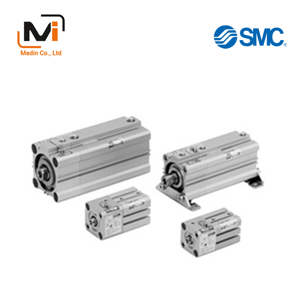
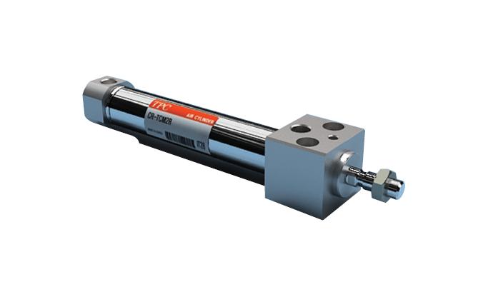
Xi Lanh Khí Nén SMC CLQ Series CDLQB20 CDLQB25 CDLQA32 40/50/63/80/100
CLQ Series Compact Cylinder With Lock, Double Acting, Single Rod enables locking at any position within the entire stroke.
Download
Xi Lanh Khí Nén SMC CLQ Series CDLQB20 CDLQB25 CDLQA32 40/50/63/80/100
CLQ Series Compact Cylinder With Lock, Double Acting, Single Rod Specifications
[Features] · Extension locking to prevent drops for press fitting jigs, etc.· Retraction locking to prevent drops for lifters and hold clamping.
· Locking position can be changed to accommodate external stopper positions and thickness of clamped workpieces.
· Simple and reliable locking system.
Model Number Notation
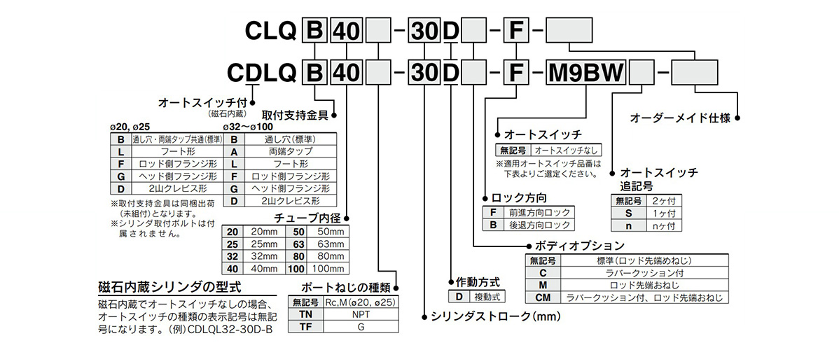
How to order: image
Applicable auto switches
| Type | Auto Switch Unit Part Number | Special Functions | Lead wire entry |
Indi- cator light |
Wiring (Output) | Load voltage | |||||||
|---|---|---|---|---|---|---|---|---|---|---|---|---|---|
| Perpendicular | In-line | DC | AC | ||||||||||
| ø20 (20‑mm diameter), ø25 (25‑mm diameter) | ø32 (32-mm diameter) to ø100 (100-mm diameter) | ø20 mm | ø25 (25-mm diameter) | ø32 mm | ø40 (40-mm diameter) to ø100 (100-mm diameter) | ||||||||
| Solid State Auto Switch | M9NV | M9N | – | Grom- met |
Yes | 3-wire (NPN) | 24 V | 5 V, 12 V | – | ||||
| M9PV | M9P | 3-wire (PNP) | |||||||||||
| M9BV | M9B | 2-wire | 12 V | ||||||||||
| – | J79C | – | Connector | ||||||||||
| M9NWV | M9NW | Diagnostic indication (2-color indicator) | Grom- met |
3-wire (NPN) | 5 V, 12 V | ||||||||
| M9PWV | M9PW | 3-wire (PNP) | |||||||||||
| M9BWV | M9BW | 2-wire | 12 V | ||||||||||
| *1M9NAV | *1M9NA | Water-resistant (2-color indicator) |
3-wire (NPN) | 5 V, 12 V | |||||||||
| *1M9PAV | *1M9PA | 3-wire (PNP) | |||||||||||
| *1M9BAV | *1M9BA | 2-wire | 12 V | ||||||||||
| – | – | F79F | With diagnostic output (2-color indicator) | 4-wire | 5 V, 12 V | ||||||||
| – | – | P3DWA** | Magnetic field resistant (2-color indication) | 2-wire (non-polar) | – | ||||||||
| – | – | P4DW | |||||||||||
| Reed type auto switch | A96V | A96 | – | Grommet | Yes | 3-wire (NPN equivalent) | – | 5 V | – | ||||
| – | A72 | – | A72H | 2-wire | – | 200 V | |||||||
| 2A93V* | A93 | 24 V | 12V | 100V | |||||||||
| A90V | A90 | No | 5 V, 12 V | 100 V or less | |||||||||
| – | A73C | – | Connector | Yes | 12V | – | |||||||
| – | A80C | – | No | 5 V, 12 V | 24 V or less | ||||||||
| – | A79W | – | Diagnostic indication (2-color indicator) | Grommet | Yes | – | – | ||||||
| Type | Auto Switch Unit Part Number | Lead Wire Length (m) | Pre-wired Connector |
Applicable load | ||||||||||
|---|---|---|---|---|---|---|---|---|---|---|---|---|---|---|
| Perpendicular | In-line | 0.5 (Nil) |
1 (M) | 3 (L) | 5 (Z) | None (N) | ||||||||
| ø20 (20‑mm diameter), ø25 (25‑mm diameter) | ø32 (32-mm diameter) to ø100 (100-mm diameter) | ø20 mm | ø25 (25-mm diameter) | ø32 mm | ø40 (40-mm diameter) to ø100 (100-mm diameter) | |||||||||
| Solid State Auto Switch | M9NV | M9N | ● | ● | ● | ○ | – | ○ | IC circuit | Relay, PLC | ||||
| M9PV | M9P | ● | ● | ● | ○ | – | ○ | |||||||
| M9BV | M9B | ● | ● | ● | ○ | – | ○ | – | ||||||
| – | J79C | – | ● | – | ● | ● | ● | – | ||||||
| M9NWV | M9NW | ● | ● | ● | ○ | – | ○ | IC circuit | ||||||
| M9PWV | M9PW | ● | ● | ● | ○ | – | ○ | |||||||
| M9BWV | M9BW | ● | ● | ● | ○ | – | ○ | – | ||||||
| *1M9NAV | *1M9NA | ○ | ○ | ● | ○ | – | ○ | IC circuit | ||||||
| *1M9PAV | *1M9PA | ○ | ○ | ● | ○ | – | ○ | |||||||
| *1M9BAV | *1M9BA | ○ | ○ | ● | ○ | – | ○ | – | ||||||
| – | – | F79F | ● | – | ● | ○ | – | ○ | IC circuit | |||||
| – | – | P3DWA** | ● | – | ● | ● | – | ○ | – | |||||
| – | – | P4DW | – | – | ● | ● | – | ○ | ||||||
| Reed type auto switch | A96V | A96 | ● | – | ● | – | – | – | – | – | ||||
| – | A72 | – | A72H | ● | – | ● | – | – | – | – | Relay, PLC | |||
| 2A93V* | A93 | ● | ● | ● | ● | – | – | – | ||||||
| A90V | A90 | ● | – | ● | – | – | – | – | ||||||
| – | A73C | – | ● | – | ● | ● | ● | – | – | |||||
| – | A80C | – | ● | – | ● | ● | ● | – | – | |||||
| – | A79W | – | ● | – | ● | – | – | – | – | |||||
- *1Water resistant type auto switches can be mounted on the above models, but in this case, the water resistance cannot be guaranteed. Check with the manufacturer regarding water-resistant types for the above model numbers.
- *2 The type with a 1 m lead wire only supports D-A93.
- *When mounting D-A9□ (V), M9□ (V), M9□W (V) or M9□A (V) types on a side other than the port side with ø32 (32‑mm diameter) to ø50 (50‑mm diameter) cylinders, order auto switch mounting brackets separately.
- *Please note that it may not be possible to retrofit the auto switch when using mounting support brackets (foot type, head-end flange type, double clevis type).
Made to Order Specifications
| Symbols | Specifications/contents |
|---|---|
| -XA□ | Change of rod-end shape |
| -XC35 | With coil scraper, ø40 (40‑mm diameter) to 100 only |
| -XC87 | Heavy duty specification, ø40 (40‑mm diameter) to 100 only |
Cylinder Specification
| Tube Inner Diameter (mm) | 20 | 25 | 32 | 40 | 50 | 63 | 80 | 100 |
|---|---|---|---|---|---|---|---|---|
| Action | Double acting, single rod | |||||||
| Fluid | Air | |||||||
| Proof Pressure | 1.5 MPa | |||||||
| Maximum operating pressure | 1.0 MPa | |||||||
| Minimum operating pressure | 0.2 MPa*1 | |||||||
| Ambient and fluid temperature | Without auto switch: -10°C to 70°C (no freezing) With auto switch: -10 ℃ to 60°C (no freezing) |
|||||||
| Lubrication | Not required (non-lubricated) | |||||||
| Piston Speed | 50 to 500 mm/s | |||||||
| Stroke Length Tolerance | (0 to +1.0) mm*2 | |||||||
| Cushioning | None, rubber bumper | |||||||
| Port size (Rc, NPT, G) | M5 × 0.8 | 1/8 | 1/4 | 3/8 | ||||
*1: The minimum operating pressure of the cylinder is 0.1 MPa when the cylinder part and locking part are connected to separate ports.
*2: Stroke length tolerance does not include the amount of damper change.
Lock Specifications
| Tube Inner Diameter (mm) | 20 | 25 | 32 | 40 | 50 | 63 | 80 | 100 | |
|---|---|---|---|---|---|---|---|---|---|
| Locking Action | Spring locking (exhaust locking) | ||||||||
| Unlocking pressure | 0.2 MPa or more | ||||||||
| Locking Starting Pressure | 0.05 MPa or less | ||||||||
| Locking Direction | One direction (extension locking, retraction locking, each type) | ||||||||
| Unlocking port size | Rc | M5 × 0.8 | 1/8 | 1/4 | |||||
| NPT | – | ||||||||
| G | M5 × 0.8 | 1/8 | 1/4 | ||||||
| Holding force* (N) (max. static load) |
157 | 245 | 402 | 629 | 982 | 1,559 | 2,513 | 3,927 | |
| 0.5 MPa or equivalent | |||||||||
*The holding force (maximum static load) indicates the maximum capacity, not the normal holding capacity.
Standard Stroke Table
| Tube Inner Diameter (mm) | Standard Stroke (mm) |
|---|---|
| 20, 25 | 5, 10, 15, 20, 25, 30, 35, 40, 45, 50 |
| 32, 40, 50, 63, 80, 100 | 10, 15, 20, 25, 30, 35, 40, 45, 50, 75, 100 |
Diagram: ø40 (40‑mm diameter) to ø100 (100‑mm diameter)
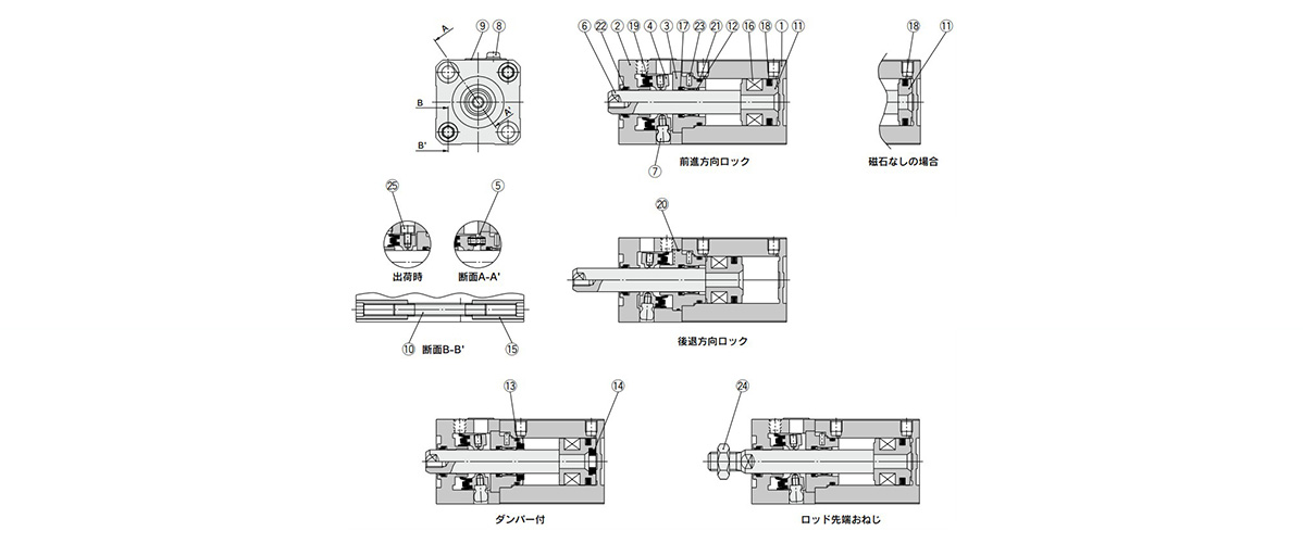
Diagram: ø40 (40‑mm diameter) to ø100 (100‑mm diameter)
*The construction above shows the locked state.
| Number | Part Name | Material | Notes |
|---|---|---|---|
| 1 | Cylinder Tube | Aluminum alloy | Hard anodized aluminum |
| 2 | Lock body | Aluminum alloy | Hard anodized aluminum |
| 3 | Intermediate collar | Aluminum alloy | Extension locking: chromated |
| Retraction locking: hard anodized | |||
| 4 | Lock ring | Carbon steel | Heat treated |
| 5 | Brake spring | Steel wire | Zinc chromate |
| 6 | Piston rod | Stainless steel | ø20 or 25 (20‑mm or 25‑mm diameter): hard chrome plated |
| Carbon steel | ø32 (32-mm diameter): hard chrome plated | ||
| 7 | Pivot | Chrome molybdenum steel | Electroless nickel plating |
| 8 | Dust cover holding bolt | Carbon steel | – |
| 9 | Dust cover | Stainless steel | – |
| 10 | Tie-rod | Rolled steel | ø20 (20-mm diameter): nickel plated |
| ø25 (25-mm diameter): zinc chromated | |||
| ø32 (32-mm diameter): black zinc chromated | |||
| 11 | Piston | Aluminum alloy | – |
| 12 | Bushing | Resin/Copper alloy (Multiple layers) | – |
| 13 | Damper A | Urethane | – |
| 14 | Damper B | Urethane | – |
| 15 | Tie-rod nut | Carbon steel | Nickel plated |
| 16 | Magnet | – | – |
| 17 | Rod packing | NBR | – |
| 18 | Piston packing | NBR | – |
| 19 | Lock ring seal | NBR | – |
| 20 | Tube gasket A | NBR | – |
| 21 | Tube gasket B | NBR | – |
| 22 | Scraper | NBR | – |
| 23 | Parallel pin | Stainless steel | JIS B1354 |
| 24 | Rod end nut | Carbon steel | – |
| 25 | Lock release bolt | Chrome molybdenum steel | – |
Diagram: ø40 (40‑mm diameter) to ø100 (100‑mm diameter)
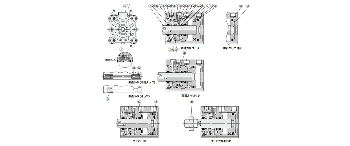
Diagram: ø40 (40‑mm diameter) to ø100 (100‑mm diameter)
*The construction above shows the locked state.
| Number | Part Name | Material | Notes |
|---|---|---|---|
| 1 | Cylinder Tube | Aluminum alloy | Hard anodized aluminum |
| 2 | Lock body | Aluminum alloy | Hard anodized aluminum |
| 3 | Intermediate collar | Aluminum alloy | Chromate |
| 4 | Lock ring | Carbon steel | Heat treated |
| 5 | Brake spring | Steel wire | Zinc chromate |
| 6 | Collar | Aluminum bearing alloy | ø40 (40-mm diameter): hard anodized |
| Diecast aluminum alloy | ø50 to 100 (50‑mm to 100‑mm diameter): chromated, coated | ||
| 7 | Piston rod | Carbon steel | Hard chrome plated |
| 8 | Lever | Stainless steel | – |
| 9 | Pivot pin | Carbon steel | Zinc chromate |
| 10 | Pivot key | Carbon steel | Zinc chromate |
| 11 | Dust cover holding bolt | Chrome molybdenum steel | – |
| 12 | Dust cover holding bolt | Rolled steel | – |
| 13 | Tie-rod | Rolled steel | ø40 (40-mm diameter): zinc chromated |
| Carbon steel | ø50 (50-mm diameter) or larger: zinc chromated | ||
| 14 | Unit holding bolt | Carbon steel | Nickel plated |
| 15 | Piston | Aluminum alloy | – |
| 16 | Bushing | Resin/Copper alloy (Multiple layers) | Use ø50 (50‑mm diameter) or larger only |
| 17 | Damper A | Urethane | – |
| 18 | Damper B | Urethane | – |
| 19 | Carbon tool steel | Carbon tool steel | Phosphate conversion coating |
| 20 | Tie-rod nut | Carbon steel | ø40 (40-mm diameter): nickel plated |
| ø50 to 100 (50‑mm to 100‑mm diameter): zinc chromated | |||
| 21 | Magnet | – | – |
| 22 | Rod seal A | NBR | – |
| 23 | Rod seal B | NBR | – |
| 24 | Rod seal C | NBR | – |
| 25 | Piston seal A | NBR | – |
| 26 | Piston seal B | NBR | – |
| 27 | Tube gasket A | NBR | – |
| 28 | Tube gasket B | NBR | – |
| 29 | Scraper | NBR | – |
| 30 | Hex socket countersunk head screw | Chrome molybdenum steel | – |
| 31 | Spring pin | Carbon steel | JIS B2808 |
| 32 | Parallel pin | Stainless steel | JIS B1354 |
| 33 | Rod end nut | Carbon steel | – |
Basic Information
| Cylinder Operation Method | Double Acting | Rod Operation Method | Single Rods | Additional Function | With fall prevention function / With Intermediate Stop Function |
|---|---|---|---|---|---|
| Environment, Applications | Standard | Operating Pressure(MPa) | 0.2 to 1.0 |
CDLQB20-5D-B-M9BVL
CDLQB25-5D-F-M9BV
CDLQA32-7D-F-M9BVS
CDLQA40-10D-B-M9BL
CDLQA50-10D-F-M9B
CDLQA63-10D-B-M9BSDPC
CDLQA80-10D-B-M9BV
CDLQA100-10D-F-XC87
———————-
👉 Xem thêm sản phẩm của SMC
Liên Hệ Medin Co., Ltd
- Công ty TNHH Mễ Đình được thành lập từ năm 2006.
- Là Đại lý uỷ quyền của SMC tại Việt Nam.
- Từ đó đến nay Medin luôn là Công ty dẫn đầu về lĩnh vực Tự Động Hoá ở thị trường trong và ngoài nước với hơn 1,000 khách hàng, cùng với rất nhiều dự án lớn nhỏ cho các nhà máy sản xuất.
- Chúng tôi cung cấp cho khách hàng những giải phát tuyệt vời nhất trong việc ứng dụng Tự Động Hoá vào sản xuất
- Phương châm: “Giải pháp của chúng tôi, lợi ích của khách hàng”
- Giá trị cốt lõi: “Uy tín là sự tồn tại của chúng tôi”

- Hơn 20 năm kinh nghiệm, chúng tôi có đội ngũ kỹ sư nhiều kinh nghiệm, có khả năng tư vấn, đưa ra giải pháp có lợi nhất cho khách hàng.
- Sự tin tưởng và đồng hành của khách hàng là động lực để Medin phát triển cao hơn và xa hơn.
👉 Nếu bạn có bất kỳ yêu cầu nào, vui lòng liên hệ với chúng tôi.
☎️ Hotline: 0902782082
![]() 3 Chi nhánh tại HCM, HN, Đà Nẵng
3 Chi nhánh tại HCM, HN, Đà Nẵng
👉 Tham khảo thêm bài viết trên Fanpage
👉 Tham khảo thêm video tại kênh Youtube

