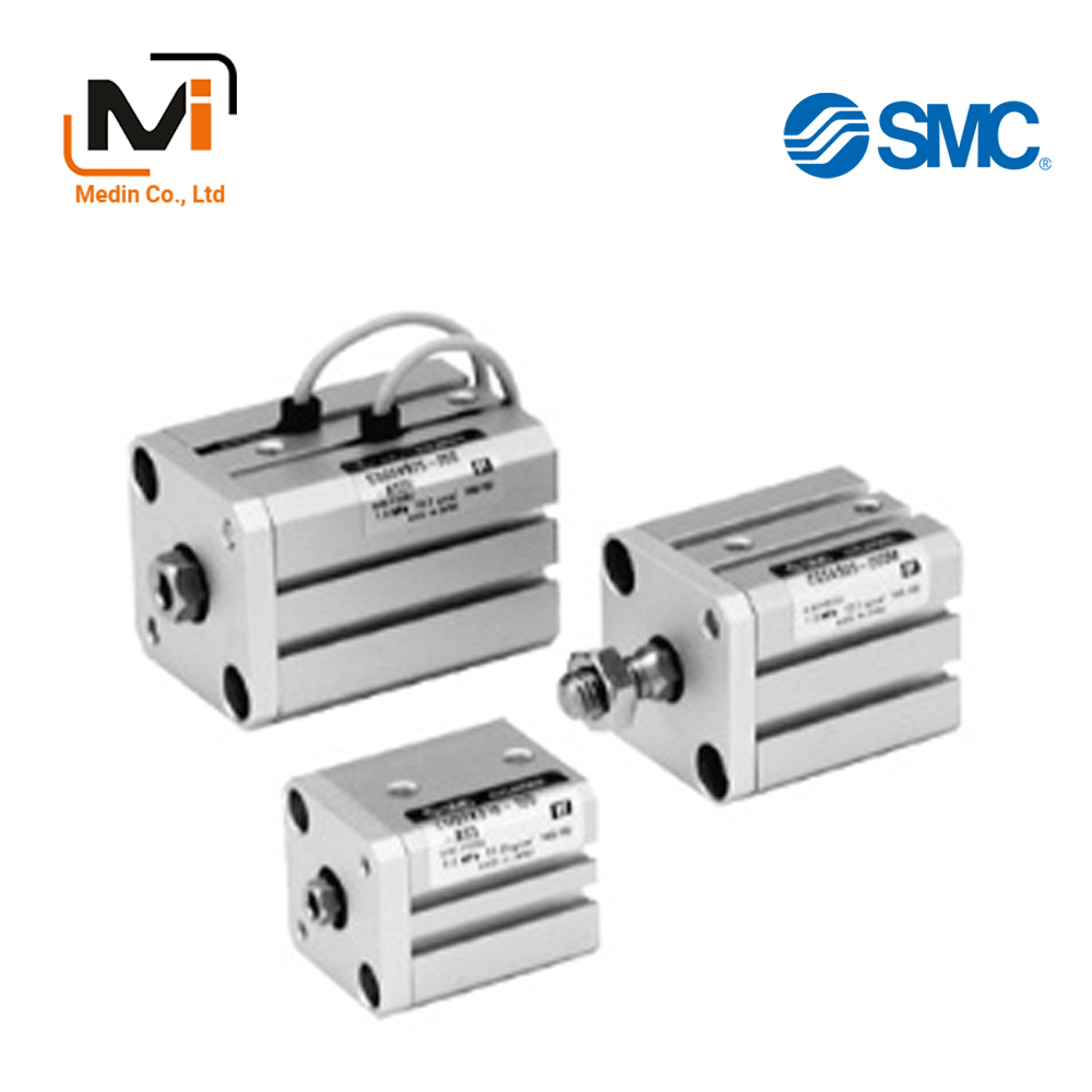
Xi Lanh Khí Nén SMC CQSK Series CDQSKB12 CDQSKB16 CDQSKB20
Compact Cylinder, Non-Rotating Rod Type, Double Acting, Single Rod CQSK Series Specifications
CQSK series that is ideal for machine designs with small space requirements.
Download
Xi Lanh Khí Nén SMC CQSK Series CDQSKB12 CDQSKB16 CDQSKB20 CDQSKB25
Compact Cylinder, Non-Rotating Rod Type, Double Acting, Single Rod CQSK Series Specifications – Xi Lanh Khí Nén SMC
[Features] · Square body shape that gives you flexibility for designing machines.· Auto switch mounting direction allows for flexible design requirements.
· 2-way basic mounting.
· Non-rotating rod with high non-rotating accuracy.
Model Number Notation

Model Number Notation
Standard specification
| Tube Internal Diameter (mm) | 12 | 16 | 20 | 25 |
|---|---|---|---|---|
| Operating method | Double acting, single rod | |||
| Applicable fluids | Air | |||
| Lubrication | Not required (non-lube) | |||
| Proof pressure | 1.5 MPa | |||
| Maximum operating pressure | 1.0 MPa | |||
| Minimum operating pressure | 0.07 MPa | 0.05 MPa | ||
| Ambient and working fluid temperature | Without auto switch: -10°C to +70°C (No freezing) | |||
| With auto switch: -10°C to +60°C (No freezing) | ||||
| Cushioning | None | |||
| Rod-end thread | Female thread | |||
| Stroke length tolerance | +1.0 mm 0 |
|||
| Operating piston speed | 50 to 500 mm/s | |||
| Allowable kinetic energy J | 0.022 | 0.038 | 0.055 | 0.09 |
| Rod non-rotating accuracy | ±1° | ±0.7° | ||
Theoretical Output List
(N)
| Bore size (mm) |
Rod width across flats (mm) |
Operating method | Piston area (mm2) |
Operating pressure (MPa) | ||
|---|---|---|---|---|---|---|
| 0.3 | 0.5 | 0.7 | ||||
| 12 | 5.2 | IN | 90 | 27 | 45 | 63 |
| OUT | 113 | 34 | 57 | 79 | ||
| 16 | 6.2 | IN | 168 | 50 | 84 | 117 |
| OUT | 201 | 60 | 101 | 141 | ||
| 20 | 8.2 | IN | 256 | 77 | 128 | 179 |
| OUT | 314 | 94 | 157 | 220 | ||
| 25 | 10.2 | IN | 401 | 120 | 200 | 281 |
| OUT | 491 | 147 | 245 | 344 | ||
Weight List / Without Auto Switch
(g)
| Bore size (mm) |
Cylinder stroke (mm) | |||||||||
|---|---|---|---|---|---|---|---|---|---|---|
| 5 | 10 | 15 | 20 | 25 | 30 | 35 | 40 | 45 | 50 | |
| 12 | 39 | 46 | 53 | 60 | 67 | 74 | – | – | – | – |
| 16 | 52 | 61 | 69 | 78 | 86 | 95 | – | – | – | – |
| 20 | 89 | 102 | 116 | 129 | 143 | 156 | 170 | 183 | 197 | 211 |
| 25 | 124 | 141 | 157 | 174 | 190 | 207 | 224 | 240 | 257 | 273 |
Weight List / With Auto Switch (Built-in Magnet)
(g)
| Bore size (mm) |
Cylinder stroke (mm) | |||||||||
|---|---|---|---|---|---|---|---|---|---|---|
| 5 | 10 | 15 | 20 | 25 | 30 | 35 | 40 | 45 | 50 | |
| 12 | 47 | 54 | 62 | 69 | 76 | 83 | – | – | – | – |
| 16 | 63 | 71 | 80 | 88 | 97 | 106 | – | – | – | – |
| 20 | 122 | 136 | 149 | 163 | 176 | 190 | 203 | 217 | 230 | 244 |
| 25 | 168 | 185 | 201 | 218 | 235 | 251 | 268 | 284 | 301 | 317 |
Structural drawing examples
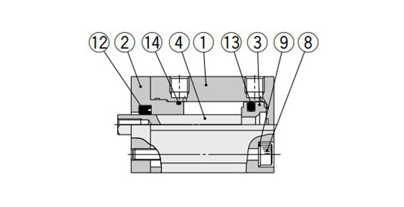
Standard ø12 (12‑mm bore size)
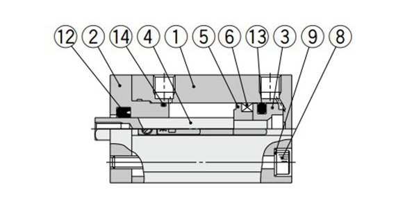
With auto switch and built-in magnet ø12 (12‑mm bore size)
Component Parts
| Number | Part name | Material | Note |
|---|---|---|---|
| 1 | Cylinder tube | Aluminum Alloy | Hard Anodize |
| 2 | Rod Cover | Aluminum Alloy | Anodized |
| 3 | Piston | Aluminum Alloy | – |
| 4 | Piston rod | Stainless steel | – |
| 5 | Spacer for switch type | Aluminum Alloy | Chromate |
| 6 | Magnet | – | – |
| 7 | Non-rotating guide | Oil-impregnated sintered alloy | ø16 (16‑mm diameter), ø20 (20‑mm diameter), ø25 (25‑mm diameter) |
| 8 | Hexagon socket head bolt | Alloy steel | Nickel plating |
| 9 | Flat washer | Rolled steel | Nickel plating |
| 10 | Rod-end nut | Carbon steel | Zinc chromate |
| 11 | Centering location ring | Aluminum Alloy | Anodized |
| 12 | Rod Gasket | NBR | – |
| 13 | Piston Gasket | NBR | – |
| 14 | Tube gasket | NBR | – |
Compact Cylinder, Non-Rotating Rod Type, Double Acting, Single Rod CQSK Series Example Dimensions
(Unit: mm)

Standard type (through-hole / both ends tapped common): ø12 (12‑mm bore size) dimensional drawing
(Unit: mm)
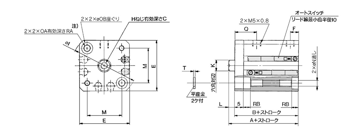
Standard type (through-hole / both ends tapped common): ø16 (16‑mm bore size) dimensional drawing

Standard type (through-hole / both ends tapped common): ø20 (20‑mm bore size) / ø25 (25 mm bore size) dimensional drawing
| Bore size (mm) |
Stroke range (mm) |
Without auto switch | With auto switch | C | E | F | H | I | K | L | M | N | OA | OB | Q | RA | RB | T | ||
|---|---|---|---|---|---|---|---|---|---|---|---|---|---|---|---|---|---|---|---|---|
| A | B | A | B | |||||||||||||||||
| 12 | 5 to 30 | 25.5 | 22 | 30.5 | 27 | 6 | 25 | 5 | M3 × 0.5 | 32 | 5.2 | 3.5 | 15.5 | 3.5 | M4 × 0.7 | 6.5 | 12.5 | 7 | 4 | 0.5 |
| 16 | 5 to 30 | 25.5 | 22 | 30.5 | 27 | 8 | 29 | 5 | M4 × 0.7 | 38 | 6.2 | 3.5 | 20 | 3.5 | M4 × 0.7 | 6.5 | 12.5 | 7 | 4 | 0.5 |
| 20 | 5 to 50 | 29 | 24.5 | 39 | 34.5 | 7 | 36 | 5.5 | M5 × 0.8 | 47 | 8.2 | 4.5 | 25.5 | 5.4 | M6 × 1.0 | 9 | 13 | 10 | 7 | 1 |
| 25 | 5 to 50 | 32.5 | 27.5 | 42.5 | 37.5 | 12 | 40 | 5.5 | M6 × 1.0 | 52 | 10.2 | 5 | 28 | 5.4 | M6 × 1.0 | 9 | 14 | 10 | 7 | 1 |
Note) For the following bore/stroke sizes, the through-hole is threaded: Standard type: ø12 (12‑mm bore size), ø16 (16‑mm bore size) 5 stroke.
Standard type: ø20 (20‑mm bore size) 5 to 15 stroke.
Standard type: ø25 (25‑mm bore size) 5 and 10 stroke.
With auto switch and built-in magnet: ø20 (20‑mm bore size) 5 stroke.
Basic Information
| Cylinder Operation Method | Double Acting | Rod Operation Method | Single Rods | Main Body Shape | Plate Cylinder |
|---|---|---|---|---|---|
| Additional Function | High rigidity / high precision high class guide / With rod detent function | Environment, Applications | Standard | Cushion | None |
CDQSKB12-2D
CDQSKB12-5D
CDQSKB12-5D-A90VLS
CDQSKB12-5D-A90VS
CDQSKB12-5D-A93VLS
CDQSKB12-5D-A93VS
CDQSKB12-5D-A96VS
CDQSKB12-5D-F8B
CDQSKB12-5D-M9BV
CDQSKB12-5D-M9BV3
CDQSKB12-5D-M9BV5
CDQSKB12-5D-M9BVL
CDQSKB12-5D-M9BVL-XC9
CDQSKB12-5D-M9BVLS
CDQSKB12-5D-M9BVM
CDQSKB16-2D
CDQSKB16-2DM
CDQSKB16-3D
CDQSKB16-3DM
CDQSKB16-4DM
CDQSKB16-5D
CDQSKB16-5D-A90VLS
CDQSKB16-5D-A90VS
CDQSKB16-5D-A93VLS
CDQSKB16-5D-A93VS
CDQSKB16-5D-M9BV
CDQSKB16-5D-M9BVL
CDQSKB16-5D-M9BVLS
CDQSKB16-5D-M9BVS
CDQSKB16-5D-M9BVZS
CDQSKB16-5D-M9NV
CDQSKB20-4D
CDQSKB20-4DM
CDQSKB20-5D
CDQSKB20-5D-A90VS
CDQSKB20-5D-A93VLS
CDQSKB20-5D-A93VS
CDQSKB20-5D-M9BV
CDQSKB20-5D-M9BVL
CDQSKB20-5D-M9BVLS
CDQSKB20-5D-M9BVM
CDQSKB20-5D-M9BVS
CDQSKB20-5D-M9BVS-XC8
CDQSKB20-5D-M9NV
CDQSKB20-5D-M9NVL
CDQSKB20-5D-M9NVLS
CDQSKB20-5D-XC8
CDQSKB25-2D
CDQSKB25-3D
CDQSKB25-4D
CDQSKB25-5D
CDQSKB25-5D-A93VLS
CDQSKB25-5D-A93VS
CDQSKB25-5D-A96VS
CDQSKB25-5D-F8B
CDQSKB25-5D-M9BV
CDQSKB25-5D-M9BVL
CDQSKB25-5D-M9BVLS
CDQSKB25-5D-M9BVM
CDQSKB25-5D-M9BVMS
CDQSKB25-5D-M9BVS
CDQSKB25-5D-M9NV
CDQSKB25-5D-M9NVL
CDQSKB25-5D-M9NVLS
———————-
👉 Xem thêm sản phẩm của SMC
Liên Hệ Medin Co., Ltd
- Công ty TNHH Mễ Đình được thành lập từ năm 2006.
- Là Đại lý uỷ quyền của SMC tại Việt Nam.
- Từ đó đến nay Medin luôn là Công ty dẫn đầu về lĩnh vực Tự Động Hoá ở thị trường trong và ngoài nước với hơn 1,000 khách hàng, cùng với rất nhiều dự án lớn nhỏ cho các nhà máy sản xuất.
- Chúng tôi cung cấp cho khách hàng những giải phát tuyệt vời nhất trong việc ứng dụng Tự Động Hoá vào sản xuất
- Phương châm: “Giải pháp của chúng tôi, lợi ích của khách hàng”
- Giá trị cốt lõi: “Uy tín là sự tồn tại của chúng tôi”

- Hơn 20 năm kinh nghiệm, chúng tôi có đội ngũ kỹ sư nhiều kinh nghiệm, có khả năng tư vấn, đưa ra giải pháp có lợi nhất cho khách hàng.
- Sự tin tưởng và đồng hành của khách hàng là động lực để Medin phát triển cao hơn và xa hơn.
👉 Nếu bạn có bất kỳ yêu cầu nào, vui lòng liên hệ với chúng tôi.
☎️ Hotline: 0902782082
![]() 3 Chi nhánh tại HCM, HN, Đà Nẵng
3 Chi nhánh tại HCM, HN, Đà Nẵng
👉 Tham khảo thêm bài viết trên Fanpage
👉 Tham khảo thêm video tại kênh Youtube


