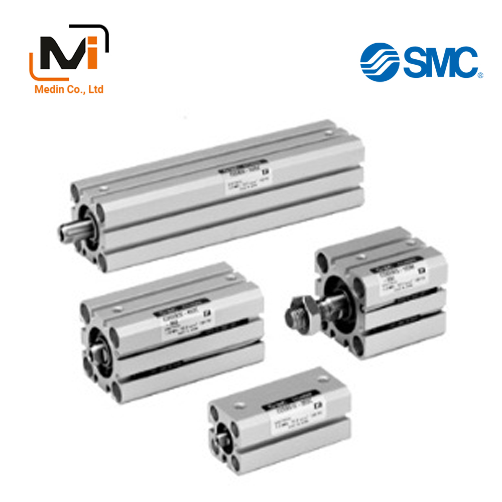
Xi Lanh Khí Nén SMC CQSY Series CDQSYB12 CDQSYB16 CDQSYB20
Smooth Cylinder CQSY Series Specifications
A special cylinder with low friction, even during bi-directional operation.
Download
Xi Lanh Khí Nén SMC CQSY Series CDQSYB12 – CDQSYB16 – CDQSYB20 – CDQSYB25
Smooth Cylinder CQSY Series Specifications
[Features] · An air cylinder with reduced stick-slip at low speed ranges.· Stable operation possible even at 5 mm/s (based on JIS B 8377).
· Lightweight and with improved functionality (new structure equivalent to the standard models).
· Interchangeable (mounting compatibility) with standard products.
*See the SMC catalog for specification details.
*Product pictures are representative images. CAD data is not supported for some model numbers.
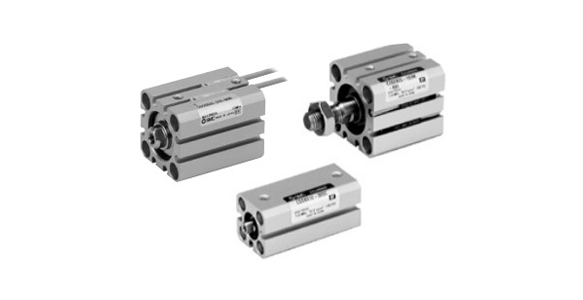
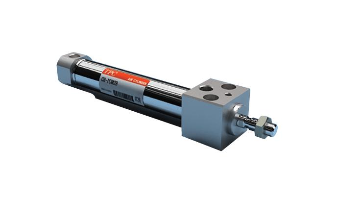
Smooth Cylinder CQSY Series external appearance
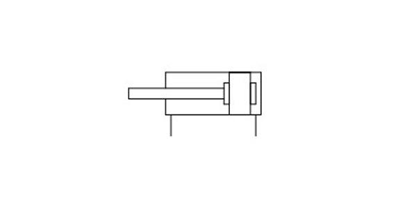
Smooth Cylinder CQSY Series JIS symbol (rubber bumper)
Specifications
| Tube Inner Diameter (mm) | 12 | 16 | 20 | 25 |
|---|---|---|---|---|
| Model | Pneumatic (non-lube) type | |||
| Action | Double acting, single rod | |||
| Fluid | Air | |||
| Proof Pressure | 1.05 MPa | |||
| Maximum operating pressure | 0.7 MPa | |||
| Ambient and Fluid Temperature | Without auto switch: -10°C to 70°C (no freezing) With auto switch: -10°C to 60°C (no freezing) |
|||
| Cushioning | Rubber cushion | |||
| Rod-end thread | Female thread | |||
| Stroke Length Tolerance | +1.0 mm* 0 |
|||
| Piston Speed | 5 to 500 mm/s | |||
| Allowable leakage rate | 0.5 L/min (ANR) or less | |||
*The stroke length tolerance does not include bumper deflection.
Minimum Operating Pressure
(Units: MPa)
| Tube Inner Diameter (mm) | 12 | 16 | 20 | 25 |
|---|---|---|---|---|
| Minimum Operating Pressure | 0.03 | 0.02 | ||
Standard Stroke Table
| Tube Inner Diameter (mm) | Standard Stroke (mm) |
|---|---|
| 12, 16 | 5, 10, 15, 20, 25, 30 |
| 20, 25 | 5, 10, 15, 20, 25, 30, 35, 40, 45, 50 |
Weight Table / Without Auto Switch
(Unit: g)
| Tube Internal Diameter (mm) |
Cylinder stroke (mm) | |||||||||
|---|---|---|---|---|---|---|---|---|---|---|
| 5 | 10 | 15 | 20 | 25 | 30 | 35 | 40 | 45 | 50 | |
| 12 | 37 | 43 | 50 | 57 | 63 | 70 | – | – | – | – |
| 16 | 49 | 57 | 66 | 74 | 83 | 92 | – | – | – | – |
| 20 | 75 | 88 | 101 | 114 | 127 | 140 | 153 | 165 | 178 | 191 |
| 25 | 109 | 125 | 140 | 156 | 172 | 188 | 204 | 220 | 236 | 252 |
With standard stroke
Calculation Example) CQSYD20-20DCM
- ¡Basic weight: CQSYB20-20DC 114 g
- Additional weight: rod end male thread 10 g
- Additional weight: double clevis type 92 g
Total 216 g
*Refer to the SMC catalog for the additional weight table.
Weight List / With Auto Switch (Built-In Magnet)
(Unit: g)
| Tube Internal Diameter (mm) |
Cylinder stroke (mm) | |||||||||
|---|---|---|---|---|---|---|---|---|---|---|
| 5 | 10 | 15 | 20 | 25 | 30 | 35 | 40 | 45 | 50 | |
| 12 | 45 | 51 | 58 | 65 | 71 | 78 | – | – | – | – |
| 16 | 59 | 67 | 76 | 85 | 94 | 103 | – | – | – | – |
| 20 | 106 | 119 | 132 | 145 | 157 | 170 | 183 | 195 | 208 | 221 |
| 25 | 151 | 167 | 183 | 199 | 215 | 231 | 246 | 262 | 278 | 294 |
Dimensions / ø12 to 25 mm
(Units: mm)
Standard Type (Through-Hole / Both Ends Tapped Common): CQSYB, CDQSYB
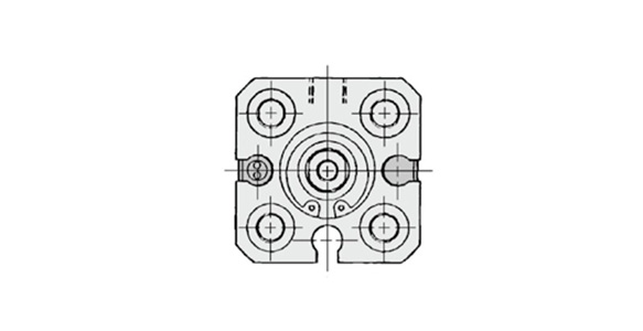
ø12 mm dimensional drawing
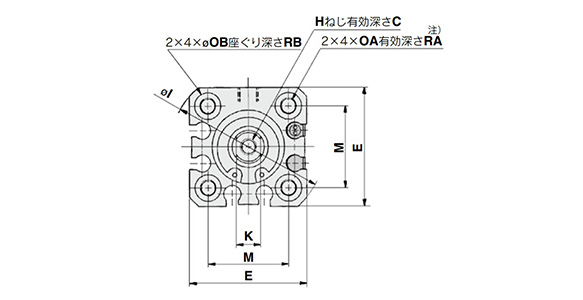
ø16 mm dimensional drawing 1
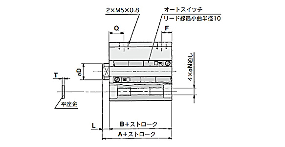
ø16 mm dimensional drawing 2
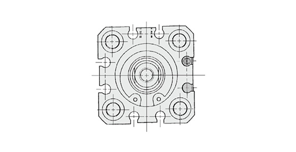
ø20 mm / ø25 mm dimensional drawing
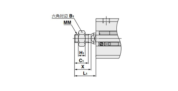
ø20 mm / ø25 mm dimensional drawing – with rod end male threading
| Tube Internal Diameter (mm) |
B1 | C1 | H1 | L1 | MM | X |
|---|---|---|---|---|---|---|
| 12 | 8 | 9 | 4 | 14 | M5 × 0.8 | 10.5 |
| 16 | 10 | 10 | 5 | 15.5 | M5 × 1.0 | 12 |
| 20 | 13 | 12 | 5 | 18.5 | M8 × 1.25 | 14 |
| 25 | 17 | 15 | 6 | 22.5 | M10 × 1.25 | 17.5 |
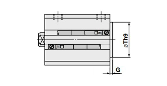
ø20 (diameter 20 mm) / ø25 (diameter 25 mm) dimensional drawing, with boss on head
| Tube Internal Diameter (mm) |
G | Th9 |
|---|---|---|
| 12 | 1.5 | 15 (-0.043 to 0) |
| 16 | 1.5 | 20 (-0.052 to 00 |
| 20 | 2 | 13 (-0.043 to 0) |
| 25 | 2 | 15 (-0.043 to 0) |
*The product with a boss on the head side is applicable only with standard strokes.
Standard type
| Tube Internal Diameter (mm) |
Stroke Range (mm) |
Without auto switch | With auto switch | C | D | E | F | H | I | K | L | M | N | OA | OB | Q | RA | RB | T | ||
|---|---|---|---|---|---|---|---|---|---|---|---|---|---|---|---|---|---|---|---|---|---|
| A | B | A | B | ||||||||||||||||||
| 12 | 5 to 30 | 25.5 | 22 | 30.5 | 27 | 6 | 6 | 25 | 5 | M3 × 0.5 | 32 | 5 | 3.5 | 15.5 | 3.5 | M4 × 0.7 | 6.5 | 7.5 | 7 | 4 | 0.5 |
| 16 | 5 to 30 | 25.5 | 22 | 30.5 | 27 | 8 | 8 | 29 | 5 | M4 × 0.7 | 38 | 6 | 3.5 | 20 | 3.5 | M4 × 0.7 | 6.5 | 7.5 | 7 | 4 | 0.5 |
| 20 | 5 to 50 | 29 | 24.5 | 39 | 34.5 | 7 | 10 | 36 | 5.5 | M5 × 0.8 | 47 | 8 | 4.5 | 25.5 | 5.4 | M6 × 1.0 | 9 | 8 | 10 | 7 | 1 |
| 25 | 5 to 50 | 32.5 | 27.5 | 42.5 | 37.5 | 12 | 12 | 40 | 5.5 | M6 × 1.0 | 52 | 10 | 5 | 28 | 5.4 | M6 × 1.0 | 9 | 9 | 10 | 7 | 1 |
*For the following bore/stroke sizes, the through-hole is threaded – Standard type: ø20 mm; 5 to 10 stroke and ø25 mm; 5 stroke.
*See the SMC catalog for dimensional drawings and dimensions tables not detailed above.
Basic Information
| Cylinder Operation Method | Double Acting | Rod Operation Method | Single Rods | Main Body Shape | Plate Cylinder |
|---|---|---|---|---|---|
| Additional Function | Standard | Environment, Applications | Low Friction (Internal Resistance) | End Locking | No |
| Cushion | Rubber cushion |
CDQSYB12-5DC-A93VLS
CDQSYB12-5DC-A93VS
CDQSYB12-5DC-M9BV
CDQSYB12-5DC-M9BVL
CDQSYB12-5DC-M9BVLS
CDQSYB12-5DC-M9BVM
CDQSYB12-5DC-M9BVS
CDQSYB12-5DC-M9NV
CDQSYB12-5DC-M9NVLS
CDQSYB12-5DC-M9NVS
CDQSYB12-5DC-M9PV
CDQSYB12-5DCM
CDQSYB12-5DCM-M9BV
CDQSYB12-5DCM-M9BVL
CDQSYB12-5DCM-M9BVM
CDQSYB12-5DCM-M9BVSAPC
CDQSYB16-5DC
CDQSYB16-5DC-A93VLS
CDQSYB16-5DC-A93VS
CDQSYB16-5DC-M9BV
CDQSYB16-5DC-M9BVL
CDQSYB16-5DC-M9BVLS
CDQSYB16-5DC-M9BVS
CDQSYB16-5DC-M9NV
CDQSYB16-5DC-M9NVS
CDQSYB16-5DC-M9PVL
CDQSYB16-5DCM
CDQSYB16-5DCM-A93VLS
CDQSYB16-5DCM-M9BV
CDQSYB16-5DCM-M9BVL
CDQSYB16-5DCM-M9BVLS
CDQSYB16-5DCM-M9NV
CDQSYB20-5DC
CDQSYB20-5DC-A93VS
CDQSYB20-5DC-M9BV
CDQSYB20-5DC-M9BVL
CDQSYB20-5DC-M9NV
CDQSYB20-5DC-M9NVS
CDQSYB20-5DC-M9PV
CDQSYB20-5DCM
CDQSYB20-5DCM-A93VLS
CDQSYB20-5DCM-M9BVLS
CDQSYB20-5DCM-M9NV
CDQSYB20-5DCM-M9NVS
CDQSYB20-10DC
CDQSYB20-10DC-A93
CDQSYB20-10DC-A93L
CDQSYB20-10DC-A93S
CDQSYB20-10DC-A93V
CDQSYB25-2DC
CDQSYB25-5DC
CDQSYB25-5DC-A93VLS
CDQSYB25-5DC-M9BV
CDQSYB25-5DC-M9BVL
CDQSYB25-5DC-M9BVLS
CDQSYB25-5DC-M9BVZS
CDQSYB25-5DC-M9NV
CDQSYB25-5DC-M9NVL
CDQSYB25-5DC-M9NVS
CDQSYB25-5DCM
CDQSYB25-5DCM-A93VLS
CDQSYB25-5DCM-M9BV
CDQSYB25-5DCM-M9BVL
CDQSYB25-5DCM-M9BVLS
CDQSYB25-5DCM-M9BVZ
———————-
👉 Xem thêm sản phẩm của SMC
Liên Hệ Medin Co., Ltd
- Công ty TNHH Mễ Đình được thành lập từ năm 2006.
- Là Đại lý uỷ quyền của SMC tại Việt Nam.
- Từ đó đến nay Medin luôn là Công ty dẫn đầu về lĩnh vực Tự Động Hoá ở thị trường trong và ngoài nước với hơn 1,000 khách hàng, cùng với rất nhiều dự án lớn nhỏ cho các nhà máy sản xuất.
- Chúng tôi cung cấp cho khách hàng những giải phát tuyệt vời nhất trong việc ứng dụng Tự Động Hoá vào sản xuất
- Phương châm: “Giải pháp của chúng tôi, lợi ích của khách hàng”
- Giá trị cốt lõi: “Uy tín là sự tồn tại của chúng tôi”

- Hơn 20 năm kinh nghiệm, chúng tôi có đội ngũ kỹ sư nhiều kinh nghiệm, có khả năng tư vấn, đưa ra giải pháp có lợi nhất cho khách hàng.
- Sự tin tưởng và đồng hành của khách hàng là động lực để Medin phát triển cao hơn và xa hơn.
👉 Nếu bạn có bất kỳ yêu cầu nào, vui lòng liên hệ với chúng tôi.
☎️ Hotline: 0902782082
![]() 3 Chi nhánh tại HCM, HN, Đà Nẵng
3 Chi nhánh tại HCM, HN, Đà Nẵng
👉 Tham khảo thêm bài viết trên Fanpage
👉 Tham khảo thêm video tại kênh Youtube

