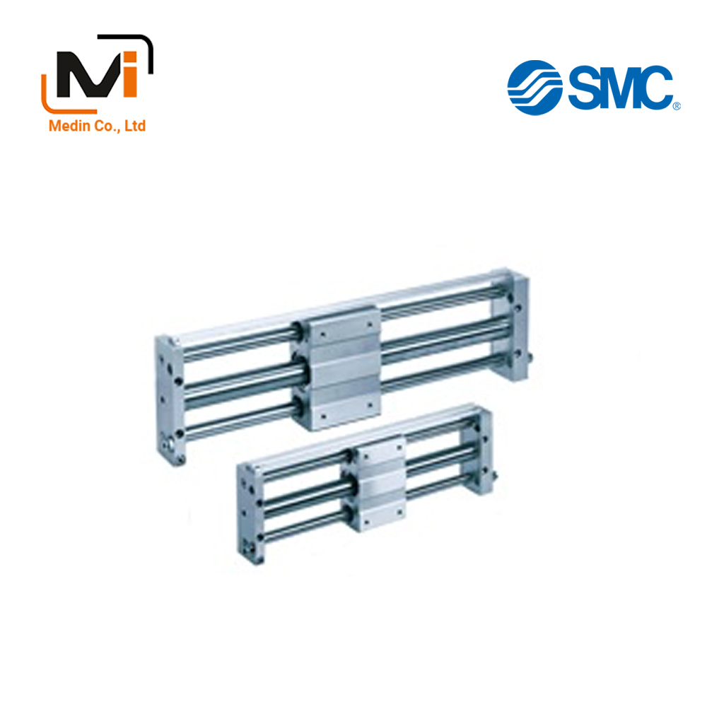
Xi Lanh Khí Nén SMC CY1L Series CY1L6H CY1L10H CY1L15H CY1L20H CY1L25H CY1L32H CY1L40H
Magnetically Coupled Rodless Cylinder, Slider Type with Ball Bushing Bearing, CY1L series by SMC.
Download
Xi Lanh Khí Nén SMC CY1L Series CY1L6H CY1L10H CY1L15H CY1L20H CY1L25H CY1L32H CY1L40H
Magnetically Coupled Rodless Cylinder, Slider Style: Ball Bushing Bearing, CY1L Series Specifications – Xi Lanh Khí Nén SMC
[Features] · Space-saving cylinder with a wide range of applications thanks to its magnet coupling structure.Model Indication Method
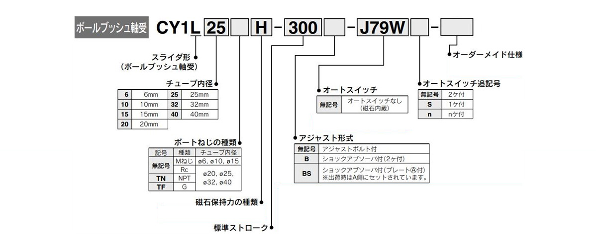
Model Indication Method
Specifications
| Tube inner diameter (mm) | 6 | 10 | 15 | 20 | 25 | 32 | 40 | |
|---|---|---|---|---|---|---|---|---|
| Usable fluids | Air | |||||||
| Guaranteed pressure resistance | 1.05 MPa | |||||||
| Maximum operating pressure | 0.7 MPa | |||||||
| Minimum operating pressure | 0.18 MPa | |||||||
| Ambient temperature and working fluid temperature | -10 to 60°C (however, no freezing) | |||||||
| *Operating piston speed | 50 to 500 mm/s | |||||||
| Cushion | Rubber cushion / shock absorber | |||||||
| Lubrication | Not required (lubrication-free) | |||||||
| Allowable difference of stroke length (mm) | 0 to 250 st: (0 to +1.0), 251 to 1,000 st: (0 to +1.4), 1,001 st and above: (0 to +1.8) | |||||||
| Type of retention force | H-type | 19.6 | 53.9 | 137 | 231 | 363 | 588 | 922 |
| L-type | – | – | 81.4 | 154 | 221 | 358 | 569 | |
| Standard equipment | Rail for mounting an auto switch | |||||||
- *If the auto switch is set in the intermediate position, whether or not the maximum detectable piston speed will be respected depends on the response time of the load (relay, sequence controller, etc.).
Standard stroke table
| Tube inner diameter (mm) | Standard stroke (mm) | Manufacturable Maximum stroke (mm) |
|---|---|---|
| 6 | 50, 100, 150 and 200 | 300 |
| 10 | 50, 100, 150, 200, 250 and 300 | 500 |
| 15 | 50, 100, 150, 200, 250, 300, 350 400, 450, 500 |
750 |
| 20 | 100, 150, 200, 250, 300, 350 400, 450, 500, 600, 700 and 800 |
1,000 |
| 25 | 1,500 | |
| 32 | ||
| 40 | 100, 150, 200, 250, 300, 350 400, 450, 500, 600, 700, 800 900 and 1,000 |
1,500 |
Note: Intermediate stroke can be adjusted in 1‑mm increments.
Structural Drawing

Slider type / ball bushing bearing CY1L6

Slider type / ball bushing bearing CY1L10 to 40
Components
| Number | Part name | Materials | Additional notes |
|---|---|---|---|
| 1 | Slide block | Aluminum alloy | Anodized aluminum |
| 2 | Plate A | Aluminum alloy | Anodized aluminum |
| 3 | Plate B | Aluminum alloy | Anodized aluminum |
| 4 | Cylinder tube | Stainless steel | – |
| 5 | Guide shaft A | Carbon steel | Hard chrome plating |
| 6 | Guide shaft B | Carbon steel | Hard chrome plating |
| 7 | Piston | Note 1)Aluminum alloy | Chromate |
| 8 | Shaft | Stainless steel | – |
| 9 | Piston-side yoke | Rolled steel | Zinc chromate |
| 10 | External moving element side yoke | Rolled steel | Zinc chromate |
| 11 | Magnet A | – | – |
| 12 | Magnet B | – | – |
| 13 | Piston nut | Carbon steel | Zinc chromate ø25 to 40 (diameter 25 to 40 mm) |
| 14 | Retaining ring | Carbon tool steel | Phosphate coated |
| 15 | Retaining ring | Carbon tool steel | Phosphate coated |
| 16 | External moving element tube | Aluminum alloy | – |
| 17 | Moving element spacer | Rolled steel | Nickel plating |
| 18 | Spacer | Rolled steel | Nickel plating |
| 19 | Ball bushing | – | – |
| 20 | Plug | Brass | Nickel plating ø25 to 40 (diameter 25 to 40 mm) only |
| 21 | Adjusting bolt A | Chrome molybdenum steel | Nickel plating |
| 22 | Adjusting bolt B | Chrome molybdenum steel | Nickel plating |
| 23 | Shock absorber | – | – |
| 24 | Hex nut | Carbon steel | Nickel plating |
| 25 | Hex nut | Carbon steel | Nickel plating |
| 26 | Hex socket head bolt | Chrome molybdenum steel | Nickel plating |
| 27 | Hex socket head bolt | Chrome molybdenum steel | Nickel plating |
| 28 | Hex socket head bolt | Chrome molybdenum steel | Nickel plating |
| 29 | Hex socket head bolt | Chrome molybdenum steel | Nickel plating |
| 30 | Switch mounting rail | Aluminum alloy | – |
| 31 | Auto switch | – | – |
| 32 | Magnet (for auto switches) | – | – |
| 33 | Steel ball | – | Size: ø6 (diameter 6 mm), ø10 (diameter 10 mm) and ø15 (diameter 15 mm) only |
| 34 | Side cover | Carbon steel | ø6 (diameter 6 mm) only |
| 35 | Grease cup | Carbon steel | ø15 (diameter 15 mm) and above |
| 36 | Wear ring A | Special resin | – |
| 37 | Wear ring | Special resin | – |
| 38 | Wear ring B | Special resin | – |
| 39 | Cylinder tube gasket | NBR | – |
| 40 | Guide shaft gasket | NBR | – |
| 41 | Piston packing | NBR | – |
| 42 | Scraper | NBR | – |
Note 1: Brass, in the case of ø6 (diameter 6 mm).
Magnet Type Rodless Cylinder, Slider Type, Ball Bushing Bearing, CY1L Series Sample Dimensions
(Unit: mm)
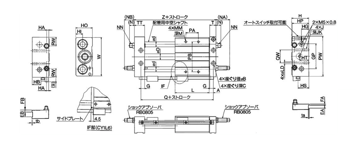
Dimensional drawing of the slider type / ball bushing bearing, CY1L6, 10
| Model | A | B | C | D | d | EA | EB | FA | FB | G | GP | H | HA | HB | HG | HI | HO | HP | HS | HT | J | JK |
|---|---|---|---|---|---|---|---|---|---|---|---|---|---|---|---|---|---|---|---|---|---|---|
| CY1L6 | 7 | 6.5 | 3 | 7.6 | 8 | – | – | – | – | 6 | 36 | 27 | 5 | 10 | 11 | 9 | 25 | 26 | 14 | 16 | M4 × 0.7 | 6.5 |
| CY1L10 | 8.5 | 8 | 4 | 12 | 10 | 6 | 12 | 3 | 5 | 7.5 | 50 | 34 | 6 | 17.5 | 14.5 | 13.5 | 33 | 33 | 21.5 | 18 | M5 × 0.8 | 9.5 |
| Model | L | LD | M | MM | (N) | (NA) | (NB) | NN | *PA | PB | PW | Q | QW | RW | T | TT | ta | tb | W | Z |
|---|---|---|---|---|---|---|---|---|---|---|---|---|---|---|---|---|---|---|---|---|
| CY1L6 | 40 | 3.5 | 6 | M4 × 0.7 | 11 | 30 | 24 | M8 × 1.0 | 24 | 40 | 60 | 54 | 20 | 12 | 10 | 16 | – | – | 56 | 68 |
| CY1L10 | 68 | 4.3 | 8 | M4 × 0.7 | 10.5 | 27 | 19 | M8 × 1.0 | 30 | 60 | 80 | 85 | 26 | 17.5 | 12.5 | 20.5 | 0.5 | 1.0 | 77 | 103 |
- *PA dimensions are halved at center.
Usage precautions
- *Beware of the space between the plate and the slide block.
- *Do not apply a load to the cylinder larger than the allowable value of the selected materials.
- *Avoid use in environments that may cause the degradation of cylinder lubricity. This includes environments where liquids such as water or machining fluids are present, environments where water vapor is present, or those where the adherence of contaminants or dust on the cylinder may be a concern.
- *When greasing up the cylinder, use the same grease as that already applied to the product.
Basic Information
| Type | Rodless Cylinder | Table Material | Aluminum Alloy | Rodless Cylinder Joint Type | Magnetic |
|---|---|---|---|---|---|
| Environment | General Purpose | Table Surface Treatment | Alumite | Guide Type | Ball bushing bearing |
| Switch Rail | Yes | Specifications | Magnet built-in | Custom-made Specifications | 0.18 to 0.7 |
CY1L6H-40
CY1L6H-45
CY1L6H-50
CY1L6H-50-A72
CY1L6H-50-A72H
CY1L6H-50-A72HL
CY1L6H-50-A72L
CY1L6H-50-A73
CY1L6H-50-A73C
CY1L6H-50-A73CL
CY1L6H-50-A73H
CY1L6H-50-A73HL
CY1L6H-50-A73HS
CY1L6H-50-A73L
CY1L6H-50-A76H
CY1L6H-50-A76HL
CY1L6H-50-A80
CY1L6H-50-A80C
CY1L6H-50-A80CL
CY1L6H-50-A80H
CY1L6H-50-A80HL
CY1L6H-50-A80L
CY1L6H-50-F7BV
CY1L6H-50-F7BVL
CY1L6H-50-F7BVL-X4
CY1L10H-30-A80H-X431
CY1L10H-30-J79-X431
CY1L10H-30B-J79-X431
CY1L10H-30B-J79L-X431
CY1L10H-30B-X431
CY1L10H-40
CY1L10H-42
CY1L10H-43
CY1L10H-50
CY1L10H-50-A72
CY1L10H-50-A72H
CY1L10H-50-A72HL
CY1L10H-50-A72L
CY1L10H-50-A73
CY1L10H-50-A73C
CY1L10H-50-A73CL
CY1L15H-25-J79W-X431
CY1L15H-25-J79WS
CY1L15H-25-X431
CY1L15H-25B
CY1L15H-25B-J79WS
CY1L15H-35-J79-X431
CY1L15H-35B
CY1L15H-35B-J79-X431
CY1L15H-40
CY1L15H-45
CY1L15H-50
CY1L15H-50-A72
CY1L15H-50-A72H
CY1L15H-50-A72HL
CY1L15H-50-A72L
CY1L15H-50-A73
CY1L20H-25-J79WS
CY1L20H-35
CY1L20H-50
CY1L20H-50-A73
CY1L20H-50-A73L
CY1L20H-50-F7BAVL
CY1L20H-50-F7NV
CY1L20H-50B
CY1L20H-50B-A73
CY1L20H-50B-A73HZ
CY1L20H-50B-A73L
CY1L20H-50B-F7BVL
CY1L20H-50B-F7P
CY1L25H-25
CY1L25H-30B
CY1L25H-35
CY1L25H-35B
CY1L25H-50
CY1L25H-50-A72
CY1L25H-50-A72H
CY1L25H-50-A72HL
CY1L25H-50-A72L
CY1L25H-50-A73
CY1L25H-50-A73C
CY1L25H-50-A73CL
CY1L25H-50-A73H
CY1L25H-50-A73HL
CY1L25H-50-A73L
CY1L25H-50-A80
CY1L32H-50-A72
CY1L32H-50-A72H
CY1L32H-50-A72HL
CY1L32H-50-A72L
CY1L32H-50-A73
CY1L32H-50-A73C
CY1L32H-50-A73CL
CY1L32H-50-A73H
CY1L32H-50-A73HL
CY1L32H-50-A73L
CY1L32H-50-A73S-XB9
CY1L40H-50
CY1L40H-50-A72
CY1L40H-50-A72H
CY1L40H-50-A72HL
CY1L40H-50-A72L
CY1L40H-50-A73
CY1L40H-50-A73C
CY1L40H-50-A73CL
CY1L40H-50-A73H
CY1L40H-50-A73HL
CY1L40H-50-A73L
CY1L40H-50-A80
CY1L40H-50-A80C
CY1L40H-50-A80CL
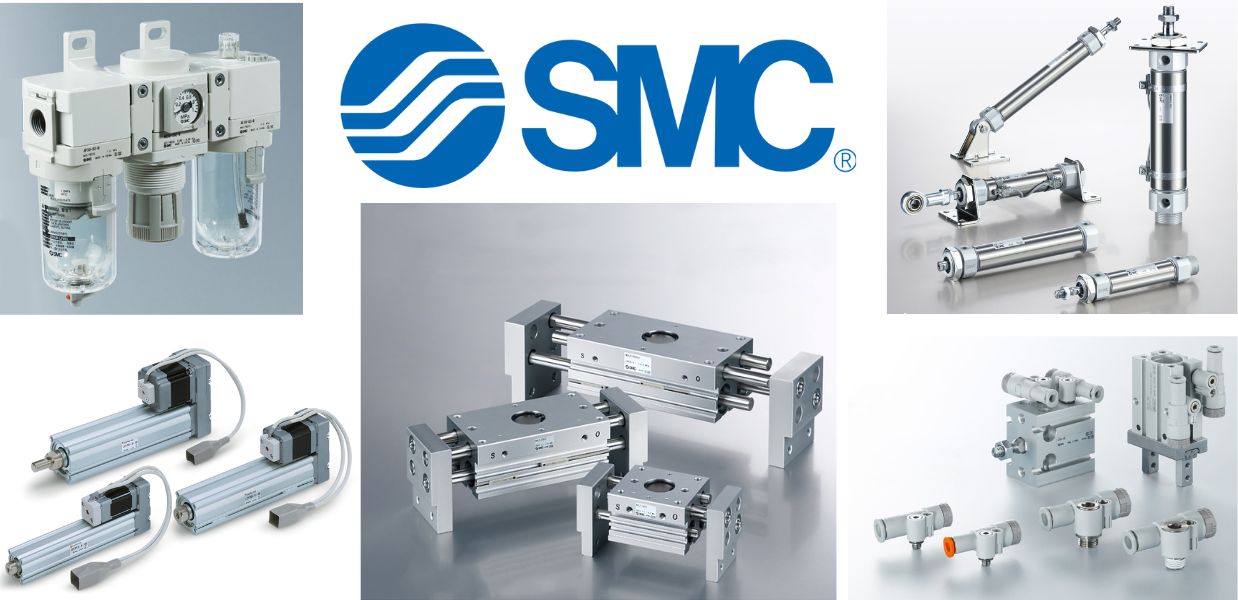
Giới thiệu SMC Việt Nam
SMC là thương hiệu hàng đầu thế giới trong lĩnh vực công nghệ khí nén, cung cấp các giải pháp tiên tiến nhằm hỗ trợ tự động hóa và tối ưu hóa quy trình sản xuất.
Với nền tảng vững chắc trong ngành, SMC Việt Nam luôn đi đầu trong việc nghiên cứu, đổi mới và phát triển sản phẩm, góp phần nâng cao năng suất và tiết kiệm lao động cho các doanh nghiệp công nghiệp.
Với phương châm “đóng góp vào tự động hóa và tiết kiệm lao động trong ngành công nghiệp”, SMC Việt Nam không ngừng cải tiến và mang đến những sản phẩm công nghệ tiên tiến nhất.
SMC Việt Nam cam kết cung cấp những giải pháp hiện đại, giúp khách hàng duy trì lợi thế cạnh tranh trên thị trường.
Medin Company cung cấp các sản phẩm SMC tại Việt Nam.
Đa dạng các sản phẩm và giải pháp khí nén phục vụ cho nhiều ngành công nghiệp khác nhau, bao gồm:
- Xy lanh khí nén – Giúp kiểm soát chuyển động chính xác và hiệu quả.
- Van điện từ – Ứng dụng rộng rãi trong điều khiển luồng khí nén.
- Bộ lọc khí nén – Đảm bảo chất lượng khí nén tối ưu.
- Cảm biến và bộ điều khiển – Tăng cường tự động hóa trong quy trình sản xuất.
———————-
👉 Xem thêm sản phẩm của SMC
Liên Hệ Medin Co., Ltd
- Công ty TNHH Mễ Đình được thành lập từ năm 2006.
- Từ đó đến nay Medin luôn là Công ty dẫn đầu về lĩnh vực Tự Động Hoá ở thị trường trong và ngoài nước với hơn 1,000 khách hàng, cùng với rất nhiều dự án lớn nhỏ cho các nhà máy sản xuất.
- Chúng tôi cung cấp cho khách hàng những giải phát tuyệt vời nhất trong việc ứng dụng Tự Động Hoá vào sản xuất
- Phương châm: “Giải pháp của chúng tôi, lợi ích của khách hàng”
- Giá trị cốt lõi: “Uy tín là sự tồn tại của chúng tôi”

- Hơn 20 năm kinh nghiệm, chúng tôi có đội ngũ kỹ sư nhiều kinh nghiệm, có khả năng tư vấn, đưa ra giải pháp có lợi nhất cho khách hàng.
- Sự tin tưởng và đồng hành của khách hàng là động lực để Medin phát triển cao hơn và xa hơn.
